GM Service Manual Online
For 1990-2009 cars only
Makes
🢒
Chevrolet
🢒
2000
🢒
Astro - 4WD
🢒
HVAC
🢒
HVAC Systems - Manual
🢒 HVAC Blower Control Schematics
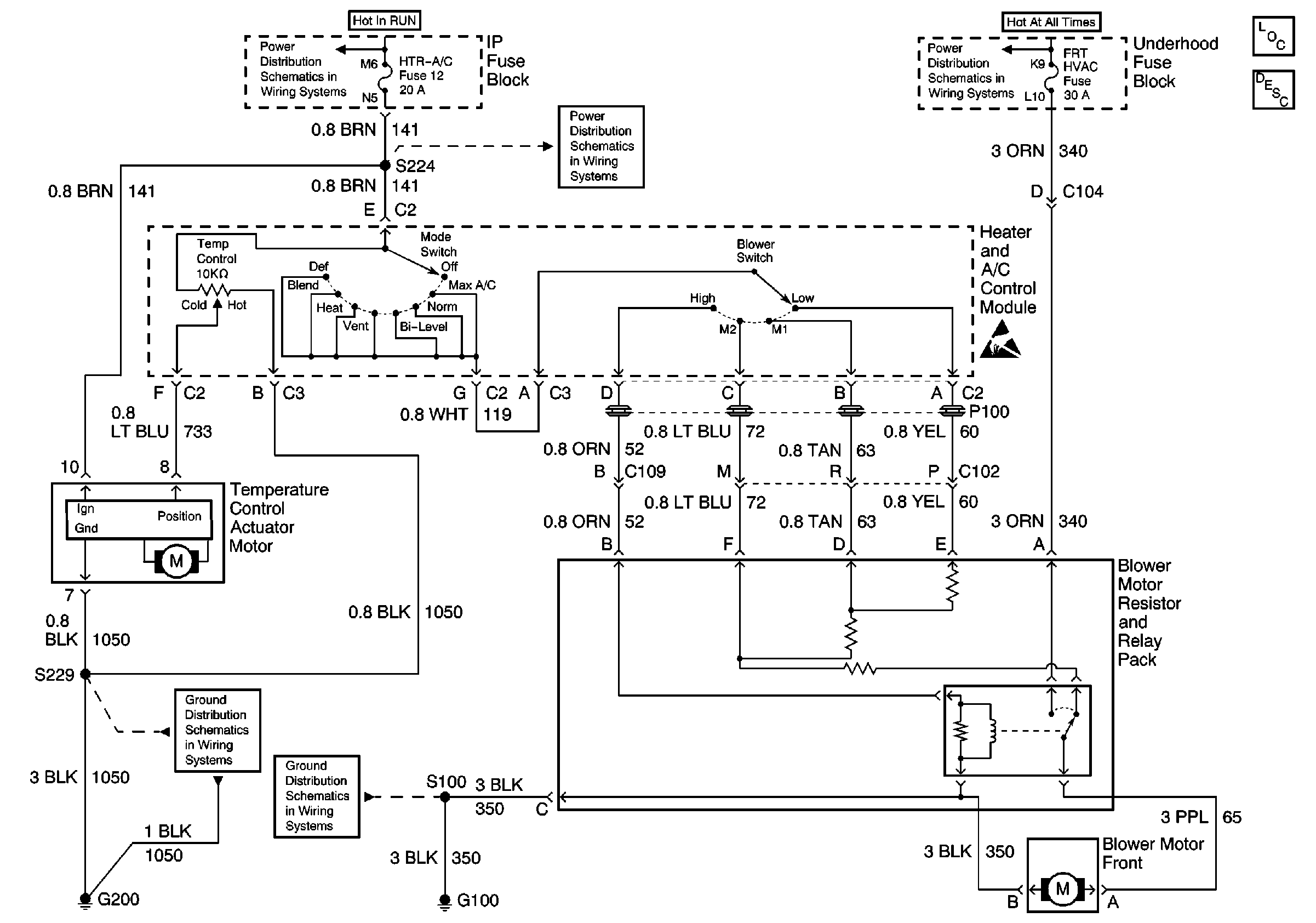
HVAC Blower Control Schematics A/C
Figure
1:
Front
HVAC Components
HVAC Blower Controls Circuit Description
Battery, Generator, Starter Solenoid, and Underhood Fuse BLock
Handling ESD Sensitive Parts Notice
HTR-A/C Fuse 12, BRAKE Fuse 18 and CRUISE Fuse 6
G200 (1 of 2)
G100, G102 and G103
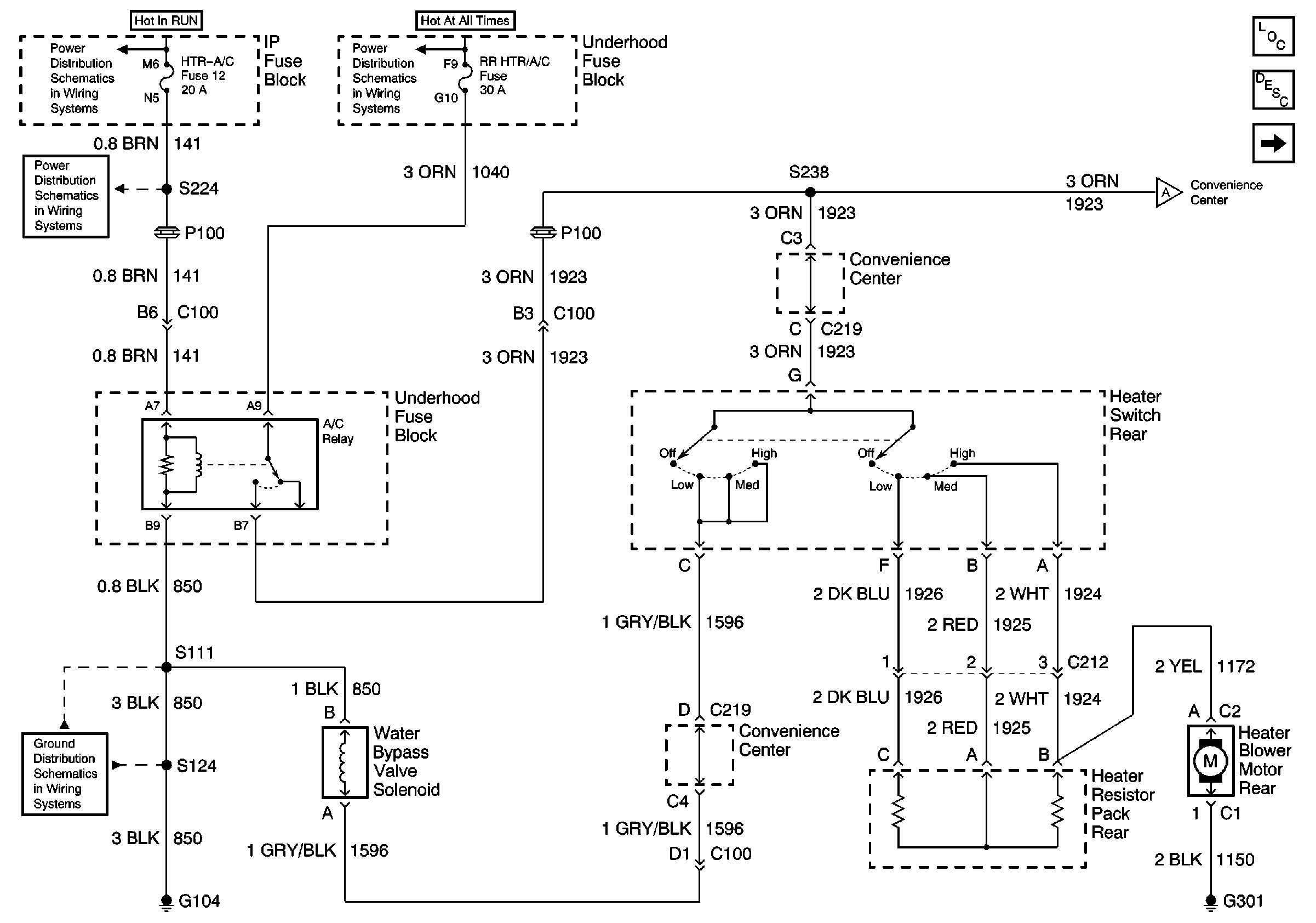
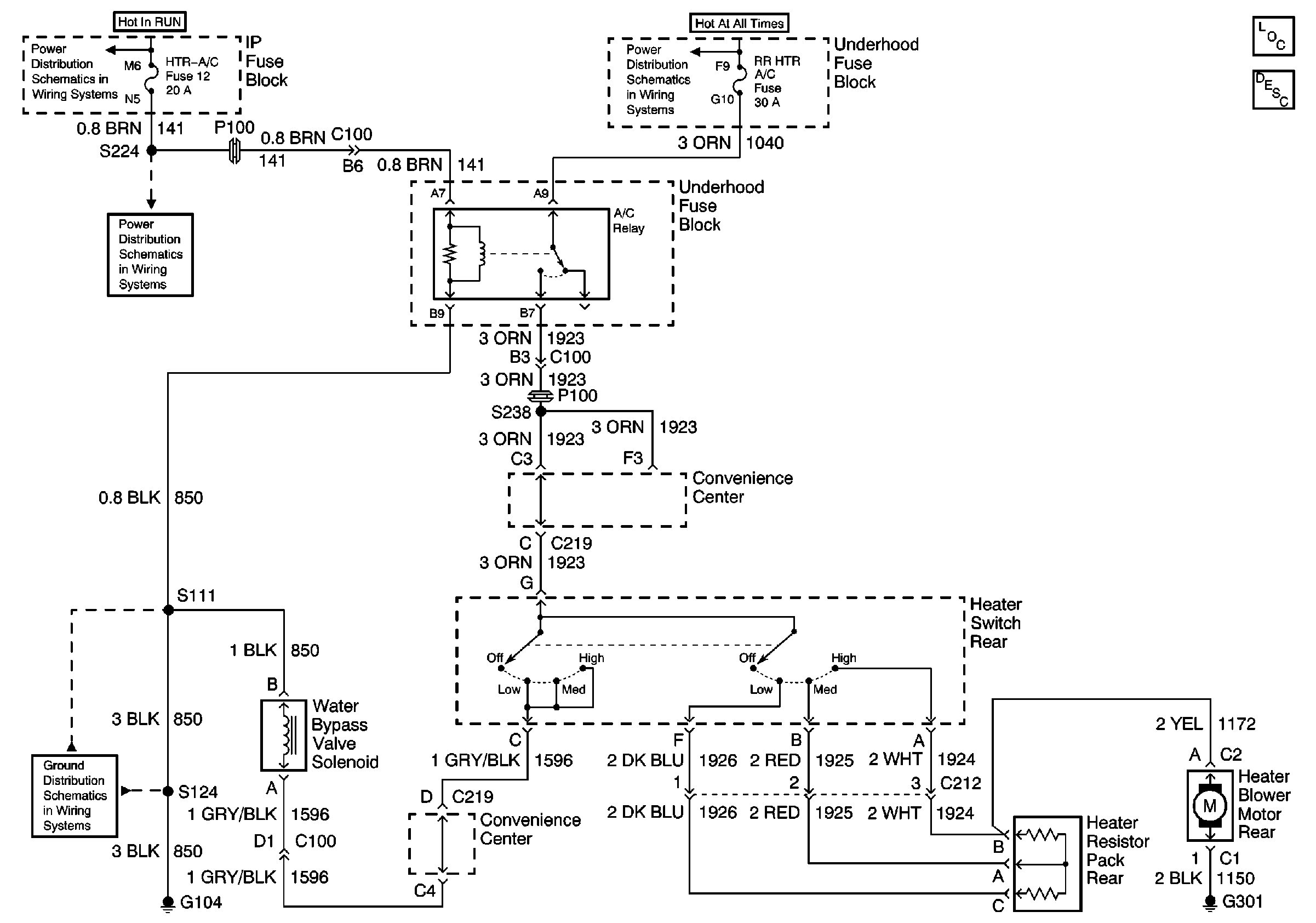
Figure
2:
Rear (1 of 2)
HVAC Components
HVAC Blower Controls Circuit Description - Auxiliary
Rear (2 of 2)
HTR-A/C Fuse 12, BRAKE Fuse 18 and CRUISE Fuse 6
Battery, Generator, Starter Solenoid, and Underhood Fuse BLock
HTR-A/C Fuse 12, BRAKE Fuse 18 and CRUISE Fuse 6
Rear (2 of 2)
G104
HTR-A/C Fuse 12, BRAKE Fuse 18 and CRUISE Fuse 6
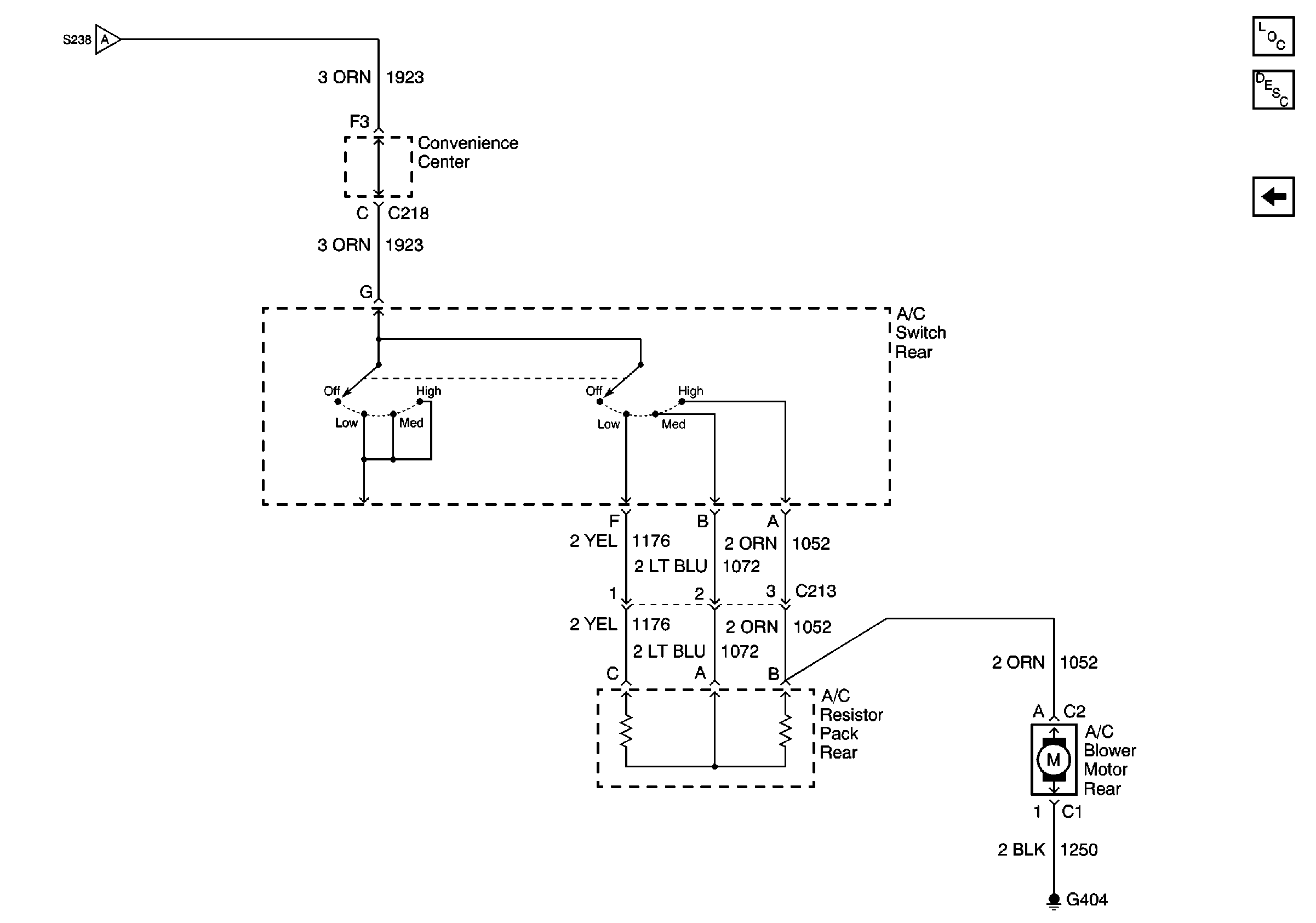
Figure
3:
Rear (2 of 2)
Rear (1 of 2)
HVAC Components
HVAC Blower Controls Circuit Description - Auxiliary
Rear (1 of 2)
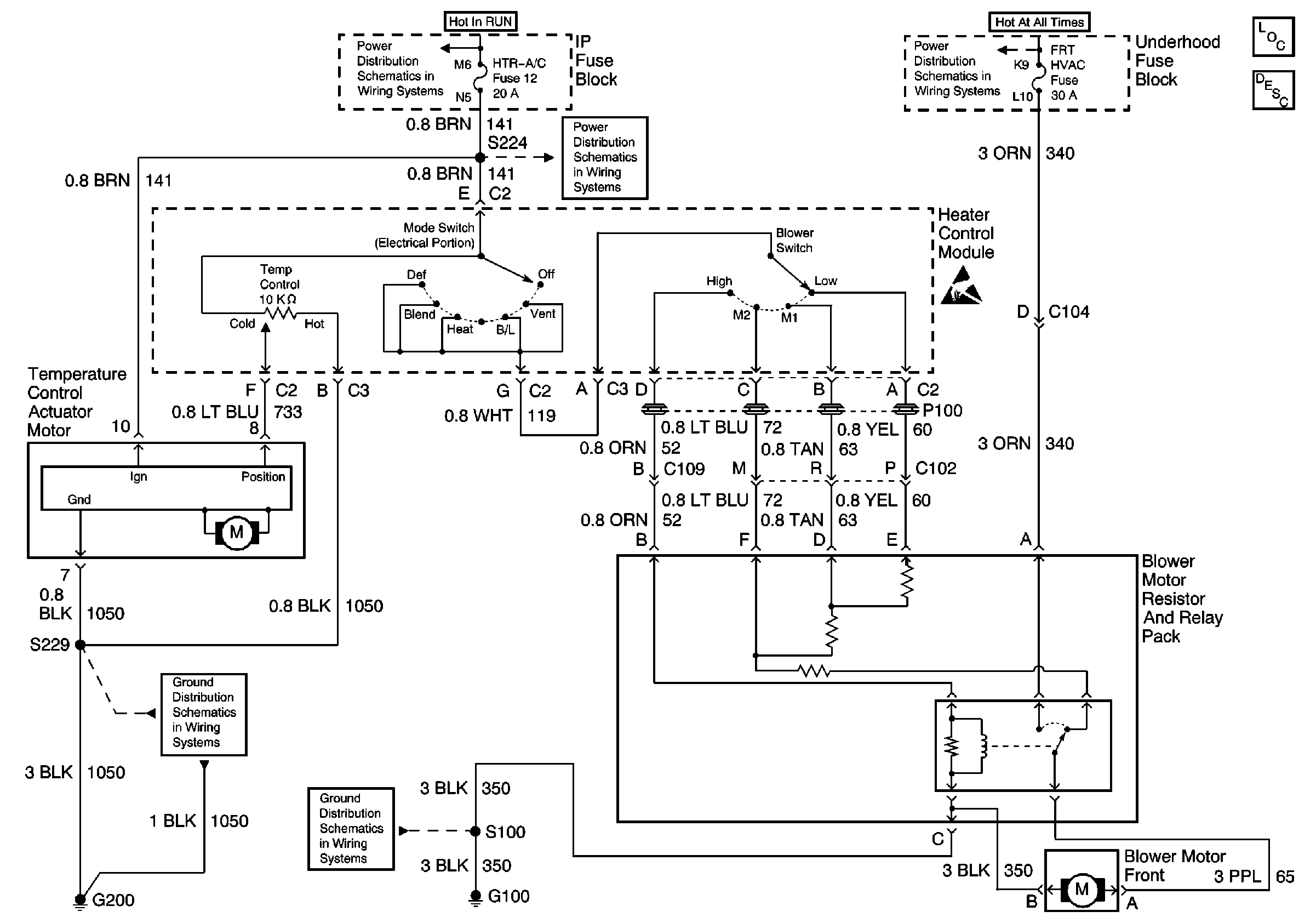
HVAC Blower Control Schematics Non-A/C
Figure
1:
Front Heater
HVAC Components
HVAC Blower Controls Circuit Description
Handling ESD Sensitive Parts Notice
HTR-A/C Fuse 12, BRAKE Fuse 18 and CRUISE Fuse 6
Battery, Generator, Starter Solenoid, and Underhood Fuse BLock
HTR-A/C Fuse 12, BRAKE Fuse 18 and CRUISE Fuse 6
G200 (1 of 2)
G100, G102 and G103
Figure
2:
Rear Heater
HVAC Components
HVAC Blower Controls Circuit Description - Auxiliary
HTR-A/C Fuse 12, BRAKE Fuse 18 and CRUISE Fuse 6
Battery, Generator, Starter Solenoid, and Underhood Fuse BLock
HTR-A/C Fuse 12, BRAKE Fuse 18 and CRUISE Fuse 6
G104