INDICATED ENGINE OVERHEAT SHORTLY AFTER START-UP

MODELS: 1987 M AND G VANS AND 1988 C/K TRUCKS WITH 4.3L (VIN CODE Z), 5.0L (VIN CODE H) AND 5.7L (VIN CODE K) ENGINES
Some 1987 , 'M' and 'G' vans and 1988 'C/K' trucks with 4.31, 5.OL, and 5.7L engines which use a serpentine accessory drive belt (and therefore a reverse rotation water pump) may experience an indicated engine overheat (temperature gage needle past the red mark) condition during warm-up. The water pumps contain highly efficient curved blade type impellers and under a certain combination of clearances, the impeller discharges a larger quantity of coolant to the right engine bank than to the left engine bank. This condition usually occurs under closed thermostat operation because the recirculating coolant flows only from the right cylinder head to the right side of the water pump. As a result, left bank coolant flow can be lower until the thermostat opens, causing the indicated overheat condition. The coolant sensor for the dash indicator is located in the left head. Excessive flow to the right bank can also cause lower coolant temperature and poor heater performance. This condition can be addressed using the following procedure.
CHECKING PROCEDURE
1. Check coolant level. 2. Check temperature sensing system (sender and gage).
An indicated overheat usually causes a swinging (between hot and cold) temperature gage needle or a needle that is stuck past the red mark.
A temperature sensing system that is working correctly will test as follows. The gage needle should be below 100 degrees Fahrenheit when engine is cold and gage needle should not be swinging below normal operating temperature when engine has be warmed up.
REPAIR PROCEDURE
1. Remove water pump using procedures in section 6B (Engine Cooling) of the approptiate service manual.
2. Remove back cover on the water pwnp by removing six machine screws.Remove gasket.
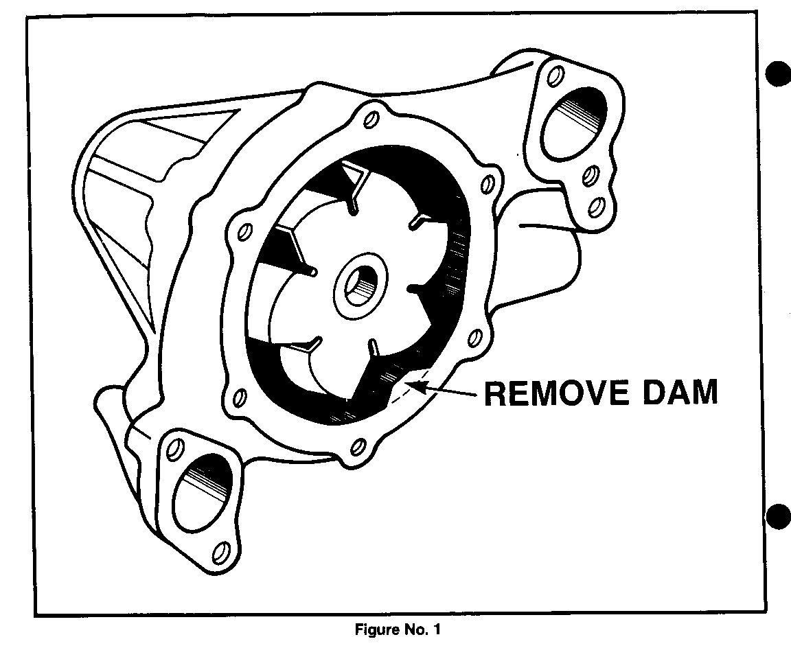
3. Using a pencil grinder, grind away the cast dam (approximately 0.150" high by about 0.5" wide) at the bottom inside of the pump body. See Figure No. 1.
a. Place rags to immobilize impeller and to gain maximum access to the dam and to keep grinding metal partides from entering the pump bearing and seal.
4. Remove metal pardcles and rags.
5. Clean pump body and cover. Reinstall back cover using a new gasket, P/N 3782611, a torque machine screws to 9 - 14 Nm (72 - 90 in).
6. Reinstall water pump.
7. Retest vehicle for condition.
Labor Operation Number: T7315 Labor Time : 1.3 Hour
Add : 0.2 A/C
Add : 0.2 P/S

General Motors bulletins are intended for use by professional technicians, not a "do-it-yourselfer". They are written to inform those technicians of conditions that may occur on some vehicles, or to provide information that could assist in the proper service of a vehicle. Properly trained technicians have the equipment, tools, safety instructions and know-how to do a job properly and safely. If a condition is described, do not assume that the bulletin applies to your vehicle, or that your vehicle will have that condition. See a General Motors dealer servicing your brand of General Motors vehicle for information on whether your vehicle may benefit from the information.
