No Start MIL ABS TCS Service Stability Service Suspension System

| Subject: | No Start, MIL, ABS, TCS, Service Stability, Service Suspension System |
| Models: | 2008 Cadillac STS w/ 4.6L LH2 Engine |
The following diagnosis might be helpful if the vehicle exhibits the symptom(s) described in this PI.
Condition/Concern:
A customer may comment they experience one or more of the following concerns.
| • | The engine does not start |
| • | The Malfunction Indicator Lamp (MIL) is on |
| • | The driver information center (DIC) displays the Service Stability message |
| • | The ABS indicator turns on |
| • | The traction control off indicator turns on |
| • | The DIC displays Service Suspension System message |
| • | The instrument panel gauges default |
| • | The DIC displays the Fuel Level Low message |
One or more of the following DTC may be stored.
C0045 | Left Rear Wheel Speed Sensor Circuit |
C0050 | Right Rear Wheel Speed Sensor Circuit |
C0186 | Lateral Accelerometer Circuit |
C0196 | Yaw Rate Circuit |
C0287 | Longitudinal Accelerometer Circuit |
C0575 | Left Front Actuator Circuit |
C0615 | Left Front Position Sensor Circuit |
C0620 | Right Front Position Sensor Circuit |
P0230 | Fuel Pump Relay Control Circuit |
P0449 | Evaporative Emission (EVAP) Vent Solenoid Control Circuit |
P0452 | Fuel Tank Pressure (FTP) Sensor Circuit Low Voltage |
P0454 | Fuel Tank Pressure (FTP) Sensor Circuit Intermittent |
P0461 | Fuel Level Sensor 1 Performance |
P0462 | Fuel Level Sensor 1 Circuit Low Voltage |
P0641 | 5 Volt Reference 1 Circuit |
P2066 | Fuel Level Sensor 2 Performance |
P2067 | Fuel Level Sensor 2 Circuit Low Voltage |
U0073 | Controller Area Network (CAN) Bus Communication |
U0100 | Lost Communication With ECM/PCM |
U0101 | Lost Communication With TCM |
U0121 | Lost Communication With Anti-Lock Brake System (ABS) Control Module |
U0140 | Lost Communication With Body Control Module |
U2100 | Controller Area Network (CAN) Bus Communication |
U2105 | Lost Communication With Engine Control Module (ECM) |
U2106 | Lost Communication With Transmission Control Module (TCM) |
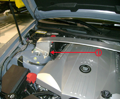
The cause may be the engine wire harness chaffing on the cross vehicle brace (1).

Recommendation/Instructions:
Repair the wire harness as required using methods found in SI Power and Signal Distribution, Wiring Systems and Power Management, Diagnostic Information and Procedures.
Please follow this diagnostic or repair process thoroughly and complete each step. If the condition exhibited is resolved without completing every step, the remaining steps do not need to be performed.
