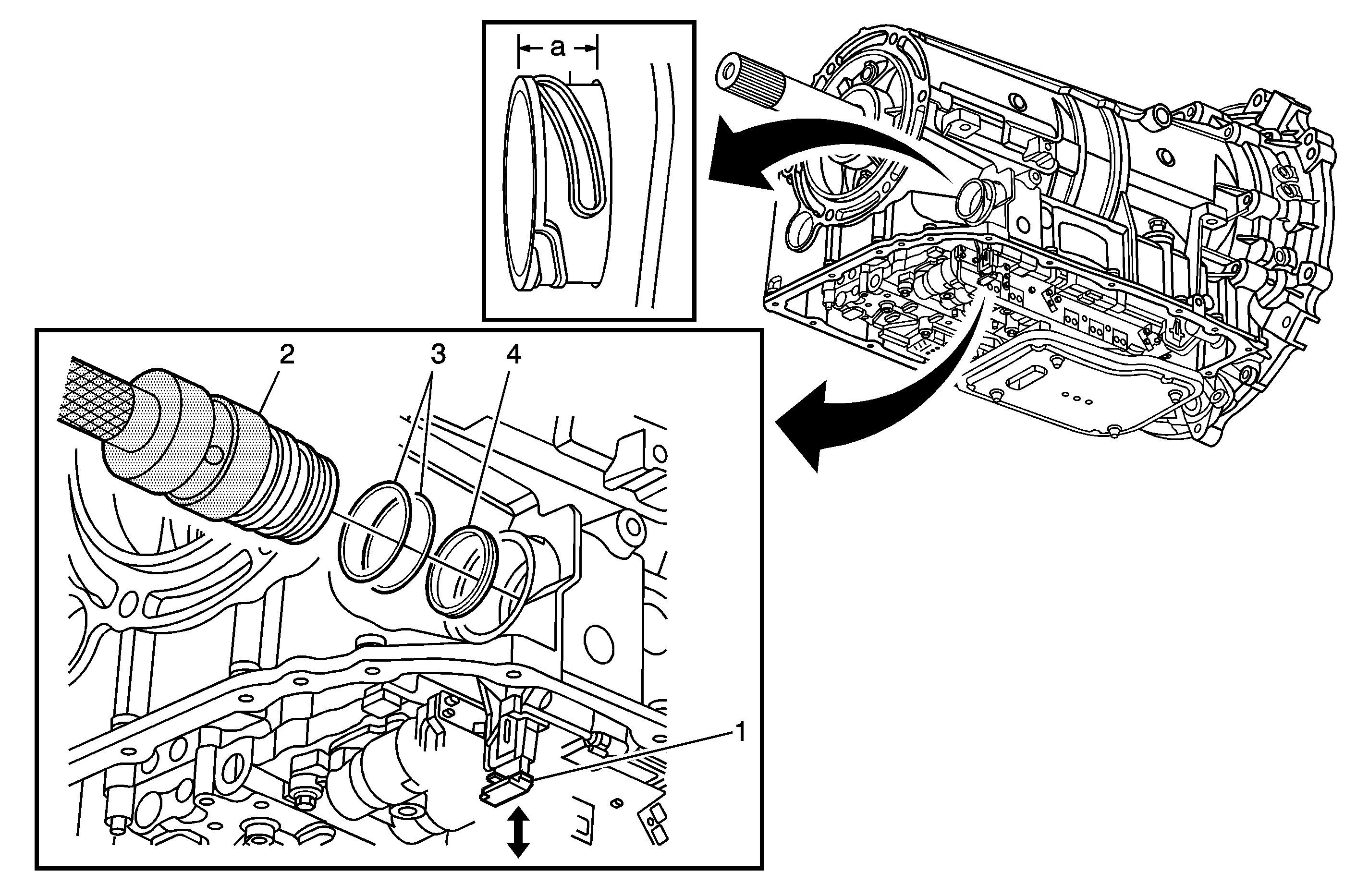
Callout | Component Name | ||||
|---|---|---|---|---|---|
|
Notice: Orientate the alignment tab inside the passage sleeve with the slot in the electrical connector of the control solenoid valve assembly. Push the sleeve straight into the case bore and connector. Do NOT rotate the sleeve at any time. Ensure the sleeve is fully seated into the case. When the sleeve is properly installed, the distance from the case surface to the end of the sleeve should be 14-16 mm. Even though the correct electrical connections may still be maintained, failure to ensure proper installation of the sleeve may result in a fluid leak around the sleeve lip seal and into the sleeve cavity. Preliminary Procedures
| |||||
1 | Electrical Connector Slide Lock Tip | ||||
2 | Electrical Connector Passage Sleeve Tip
| ||||
3 | O-Ring Seals (Qty: 2) Tip | ||||
4 | Lip Seal Tip | ||||
