SMU - Revised Air Temperature Actuator Replacement - Left Procedure

| Subject: | Revised Air Temperature Actuator Replacement - Left Procedure |
| Models: | 2004-2006 Cadillac SRX |
This bulletin is being issued to revise the Air Temperature Actuator Replacement-Left procedure in the HVAC Systems-Automatic sub-section of the Service Manual. Please replace the current information in the Service Manual with the following information.
The following information has been updated within SI. If you are using a paper version of this Service Manual, please make a reference to this bulletin on the affected page.
Air Temperature Actuator Replacement - Left
Removal Procedure
- Remove the left side closeout panel. Refer to Closeout/Insulator Panel Replacement - Left.
- Remove the left knee bolster. Refer to Knee Bolster Replacement.
- Remove the left knee bolster bracket. Refer to Knee Bolster Bracket Replacement - Left.
- If equipped with adjustable pedals, remove the 3 nuts retaining the adjustable accelerator pedal and reposition the accelerator pedal. Refer to Accelerator Pedal Assembly Replacement.
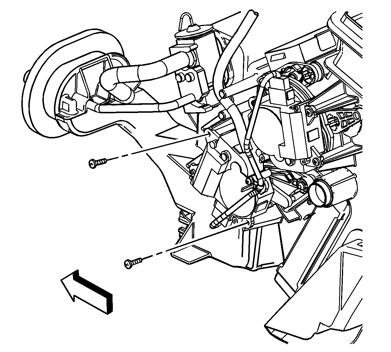
- Remove the left air temperature actuator screws.
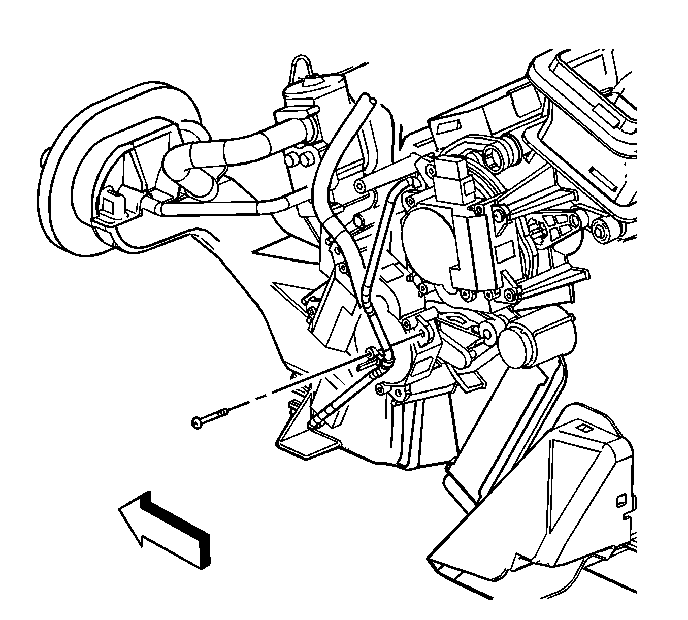
- Remove the left air temperature actuator harness screw.
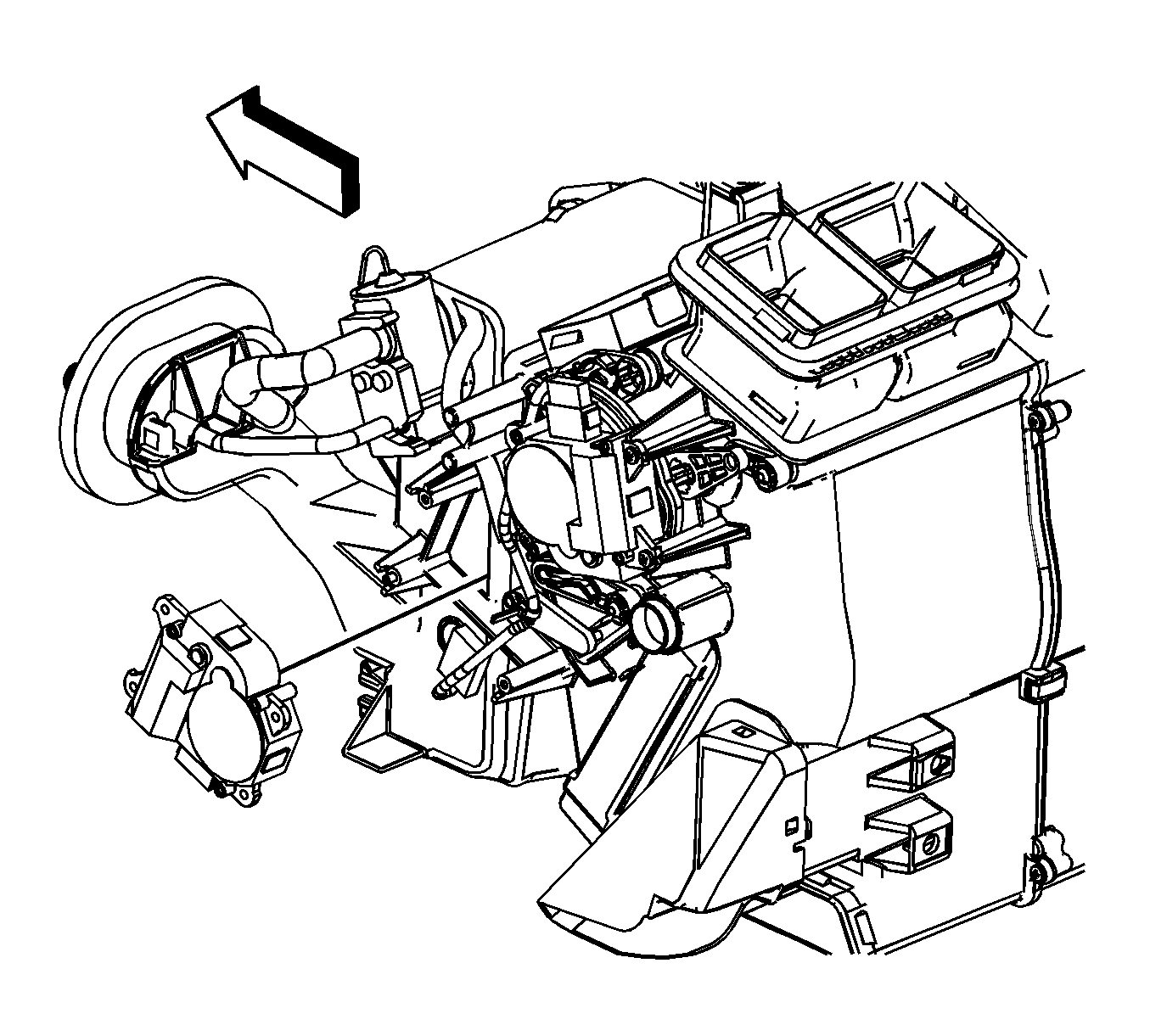
- Disconnect the left air temperature actuator electrical connector from the actuator.
- Remove the left air temperature actuator.


Installation Procedure
- Install the left air temperature actuator.
- Install the left air temperature actuator harness screw.
- Connect the left air temperature actuator electrical connector to the actuator.
- Install the left air temperature actuator screws.
- If equipped, install the adjustable accelerator pedal. Refer to Accelerator Pedal Assembly Replacement.
- Install the knee bolster bracket. Refer to Knee Bolster Bracket Replacement - Left.
- Install the knee bolster. Refer to Knee Bolster Replacement.
- Install the closeout panel. Refer to Closeout/Insulator Panel Replacement - Left.


Notice: Refer to Fastener Notice.
Tighten
Tighten the screws to 1 N·m (9 lb in).

Tighten
Tighten the screws to 1 N·m (9 lb in).
Warranty Information
Due to this procedure change, the labor time has been revised for this operation. The new labor time is reflected below.
Labor Operation | Description | Labor Time |
|---|---|---|
D1812 | Actuator A/O Motor, Elec Temp Door-Left -- Replace | 0.4 hr |
