Transmission Replacement LH2
Removal Procedure
Important: NEW torque converter bolts and cooler pipe O-rings will be required each time the transmission is removed and installed.
- Raise and support the vehicle. Refer to
Lifting and Jacking the Vehicle
.
- Remove the exhaust system. Refer to
Exhaust System Replacement
.
- Remove the rear propeller shaft. Refer to
Rear Propeller Shaft Replacement
.
- Remove the transfer case if equipped. Refer to
Transfer Case Assembly Replacement
.
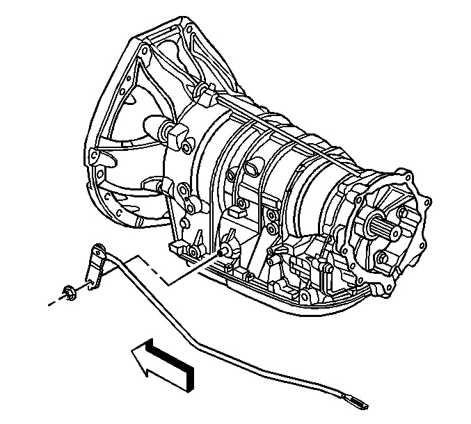
- Disconnect the shift linkage from the transmission. The linkage may be on the right or left side of the transmission
depending on the application. Refer to
Shift Control Linkage Replacement
.
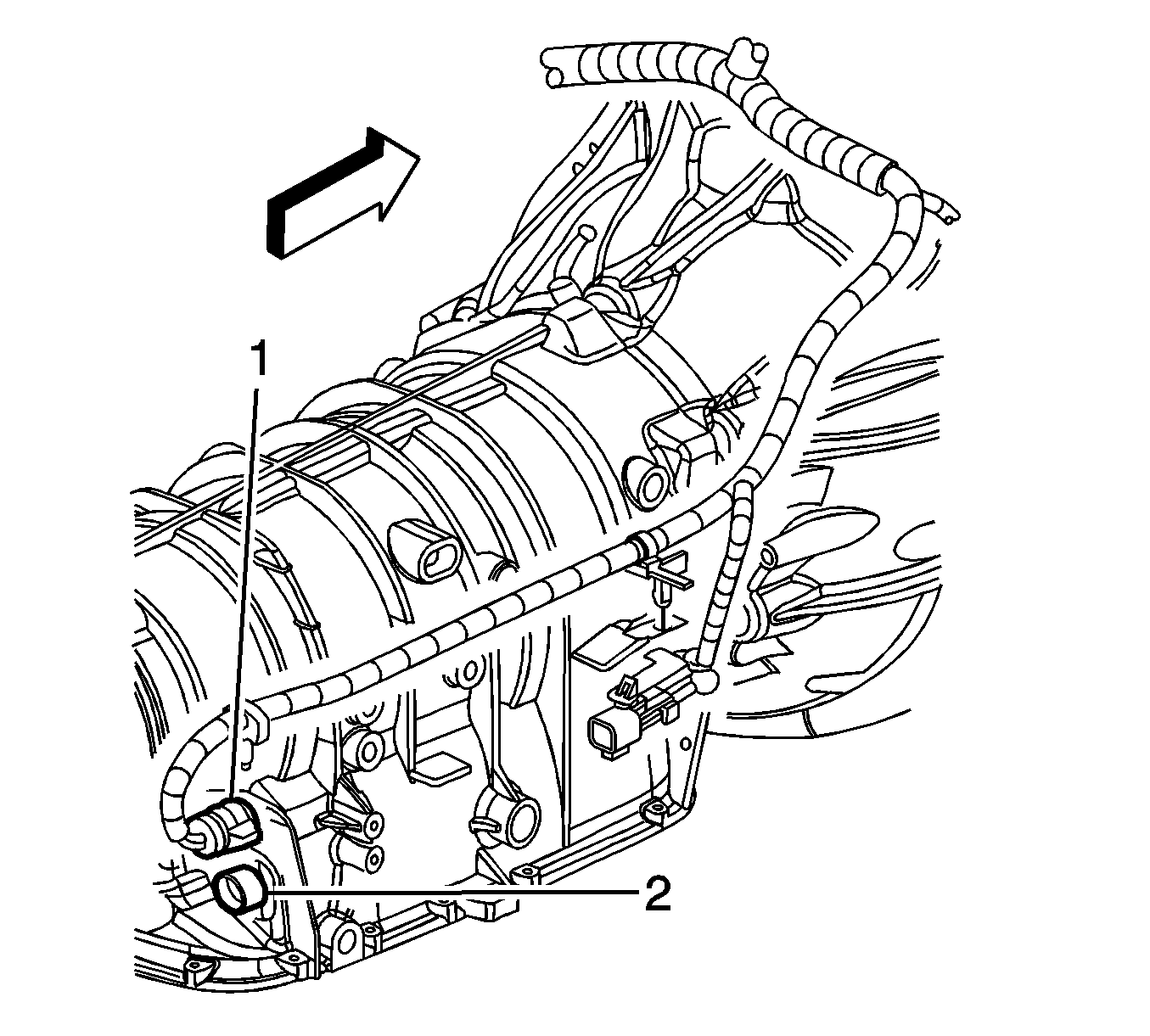
- Disconnect the transmission wiring harness connector (1) from the transmission by rotating the locking latch counterclockwise.
- Disconnect the wiring harness retainers from the transmission, and position the wiring harness aside.
- Remove the front air deflector. Refer to
Front Air Deflector Replacement
.
- Remove the transmission fluid cooler lines form the plastic cooler line retainer bracket.
- Place an oil drain pan under the transmission fluid cooler pipes.
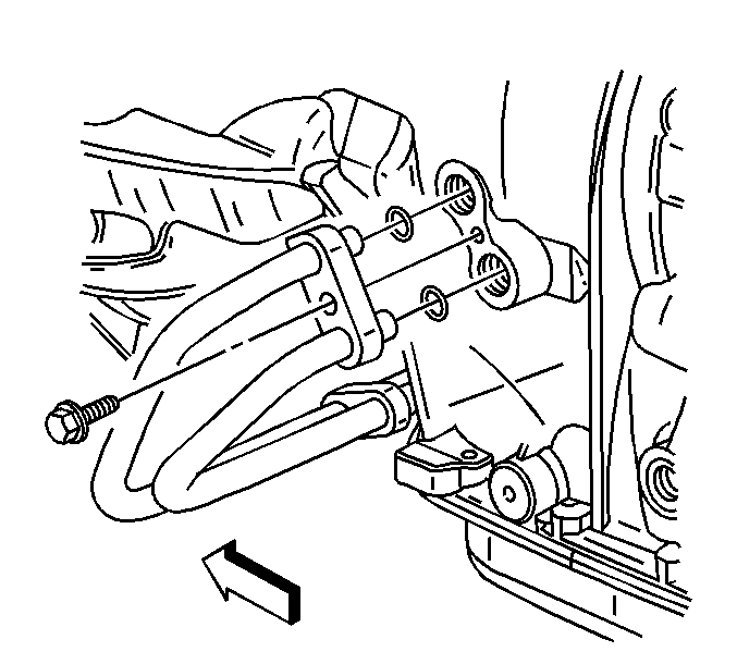
- Remove the transmission fluid cooler pipes from the transmission, and position aside. Refer to
Transmission Fluid Cooler Pipe Replacement - Rear
.
- Remove and discard the O-rings. Do NOT reuse the O-rings.
- Plug the open outlet ports to prevent fluid loss and contamination.
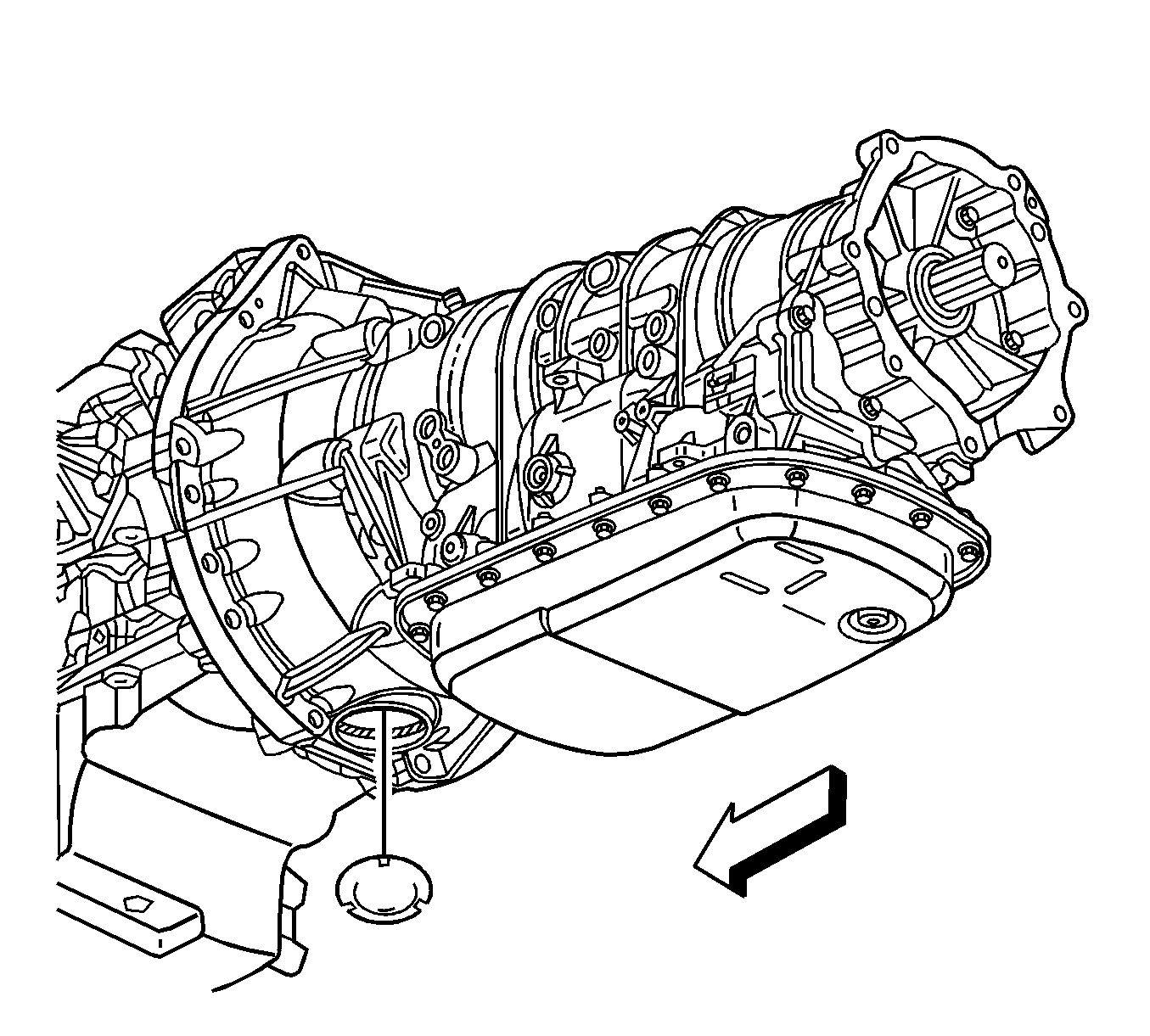
- Remove the transmission close out plug.
- Mark the torque converter to flexplate/flywheel orientation to ensure proper realignment.
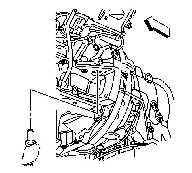
- Pull the torque converter bolt close out cover upper retaining pin downward unlocking it from the engine block.
- Remove the torque converter bolt close out cover from the engine block.
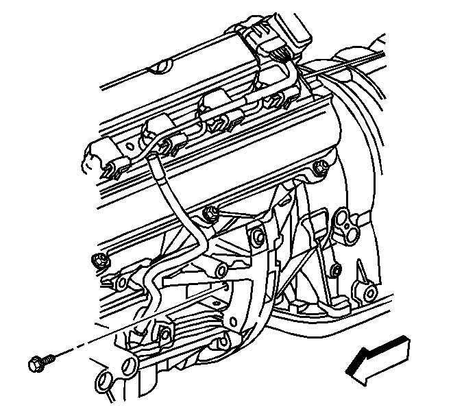
- Repeat the following steps for all 3 torque converter bolts:
| 18.1. | Rotate the harmonic balancer center bolt or fan adapter, depending on the application, clockwise ONLY, in order to align the torque converter bolt with the access hole. |
| 18.2. | Remove and discard the torque converter bolt. The bolt is self locking and is NOT reusable. |
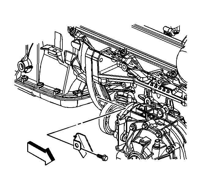
- Remove the front differential heat shield and bracket if equipped. Refer to
Shield Replacement
.
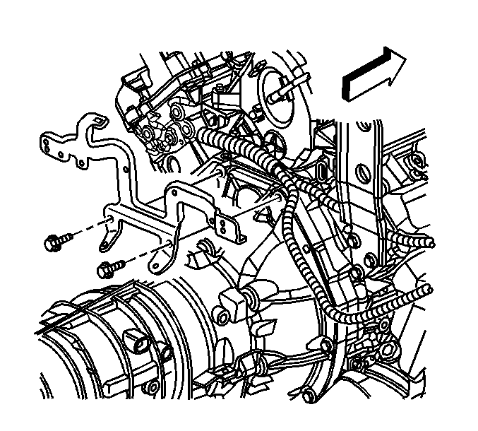
Important: Be careful to NOT allow the front differential drive pinion flange, if equipped, to come in contract with power steering rack while lowering the transmission.
- Using the transmission jack. Lower the engine and transmission assembly only enough to gain access to the upper 2 transmission mounting bolts.
- Position the engine wiring harness out of the way.
- Remove the transmission vent hose from the transmission vent tube.
- Remove the upper 2 bolts.
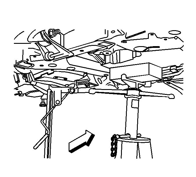
- Using the transmission jack. Raise the engine and transmission assembly to the normal position.
- Place a support stand under the rear of the engine oil pan to keep the engine level while removing the transmission.
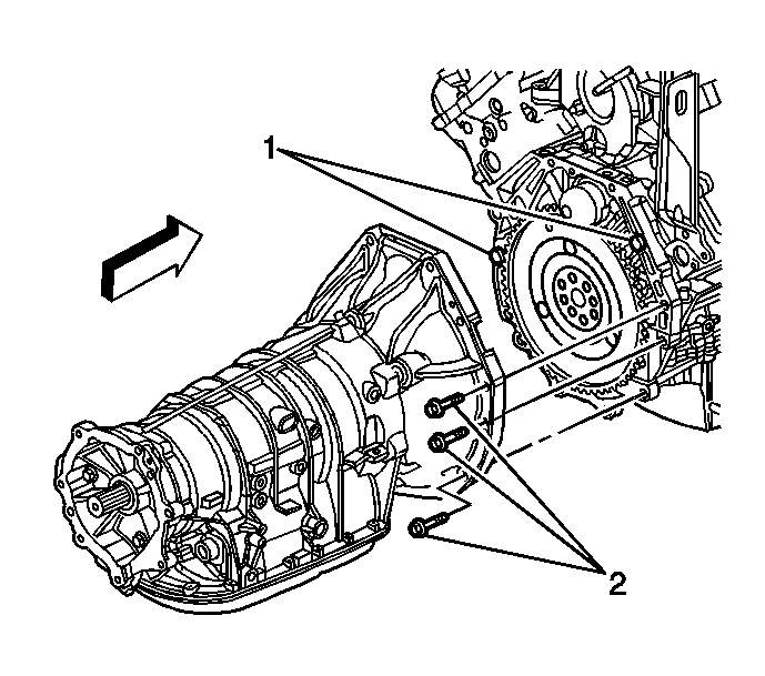
- Remove the lower 8 transmission mounting bolts.
- Pull the transmission free from the engine dowels (1).
- Separate the Transmission from the engine approximately 25.4 mm (1 in) to clear the starter drive nose cone.
Important: Ensure clearance is maintained between the transmission and the following:
| • | The starter drive nose cone |
| • | The catalytic converters |
- Carefully lower the transmission from the vehicle.
- Flush the transmission oil cooler. Refer to
Transmission Fluid Cooler Flushing and Flow Test
.
Installation Procedure
Important: Ensure clearance is maintained between the transmission and the following:
| • | The starter drive nose cone |
| • | The catalytic converters |
- Using the transmission jack, carefully raise the transmission to meet the engine.

- Align the transmission with the engine dowels (1).
Notice: Refer to Fastener Notice in the Preface section.
- Install the lower 8 transmission mounting bolts.
Tighten
Tighten the bolts to 50 N·m (37 lb ft).
- Remove the support stand from under the engine oil pan.

Important: Be careful to NOT allow the front differential drive pinion flange, if equipped, to come in contract with power steering rack while lowering the transmission.
- Using the transmission jack. Lower the engine and transmission assembly only enough to gain access to the upper transmission bolt locations.
- Install the upper transmission mounting bolts.
Tighten
Tighten the bolts to 50 N·m (37 lb ft).
- Install the transmission vent hose to the transmission vent tube.
- Position the engine wiring harness to the original location.
- Install the transfer case if equipped. Refer to
Transfer Case Assembly Replacement
.
- Align the torque converter to flexplate/flywheel orientation marks made during the removal procedure.

Important: Torque converter bolts are self locking and must be replaced with NEW torque converter bolts every time the bolts are removed.
- Complete the following steps for all 3 torque converter bolts:
| 11.1. | Rotate the harmonic balancer center bolt or the fan adapter, depending on the application, clockwise ONLY, in order to align the torque converter bolt holes in the flexplate/flywheel with the access hole in the engine block. |
| 11.2. | To aid in alignment of the torque converter to the flexplate/flywheel. Install all 3 NEW torque converter bolts before fully tightening. |
Tighten
Tighten the torque converter bolts to 60 N·m (44 lb ft).

- Install the torque converter bolt close out cover to the engine block.
- Push the torque converter bolt close out cover upper retaining pin upward locking it into the engine block.

- Install the transmission close out plug.

- Place NEW O-rings over the transmission fluid cooler pipes.
- Install the transmission fluid cooler pipes to the transmission. Refer to
Transmission Fluid Cooler Pipe Replacement - Rear
.
- Clip the transmission fluid cooler lines into the plastic cooler line retainer bracket.

- Install the front differential heat shield and bracket. Refer to
Shield Replacement
.
- Install the front air deflector. Refer to
Front Air Deflector Replacement
.

- Connect the wiring harness retainers to the transmission.
- Connect the transmission wiring harness connector (1) to the transmission by rotating the locking latch clockwise.

- Connect the shift linkage to the transmission. Refer to
Shift Control Linkage Replacement
.
- Install the rear propeller shaft. Refer to
Rear Propeller Shaft Replacement
.
- Install the exhaust system. Refer to
Exhaust System Replacement
.
- Check the transmission fluid level and fill if necessary. Refer to
Transmission Fluid Check
.
- Adjust the shift control linkage. Refer to
Shift Control Linkage Adjustment
.
- Lower the vehicle.
Transmission Final Test and Inspection
Complete the following procedure after the transmission is installed in the vehicle:
- With the ignition OFF or disconnected, crank the engine several times. Listen for any unusual noises or evidence that any parts are binding.
- Start the engine and listen for abnormal conditions.
- While the engine continues to idle, raise and support the vehicle. Refer to
Lifting and Jacking the Vehicle
.
- Inspect for fluid leaks while the engine is idling.
- Perform a final inspection for the proper fluid level.
- Lower the vehicle.
Important: It is recommended that transmission adaptive pressure (TAP) information be reset.
Resetting the TAP values using a scan tool will erase all learned values in all cells. As a result, The ECM, PCM or TCM will
need to relearn TAP values. Transmission performance may be affected as new TAP values are learned.
- Reset the TAP values. Refer to
Transmission Adaptive Functions
.
- Road test the vehicle.
Transmission Replacement LY7
Removal Procedure
Important: NEW torque converter bolts and cooler pipe O-rings will be required each time the transmission is removed and installed.
- Disconnect the negative battery cable. Refer to
Battery Negative Cable Disconnection and Connection
.
- Remove the thermostat housing to gain access to the upper transmission mounting bolts. Refer to
Engine Coolant Thermostat Housing Replacement
.
- Raise and support the vehicle. Refer to
Lifting and Jacking the Vehicle
.
- Remove the exhaust system. Refer to
Exhaust System Replacement
.
- Remove the rear propeller shaft. Refer to
Rear Propeller Shaft Replacement
.
- Remove the transfer case if equipped. Refer to
Transfer Case Assembly Replacement
.
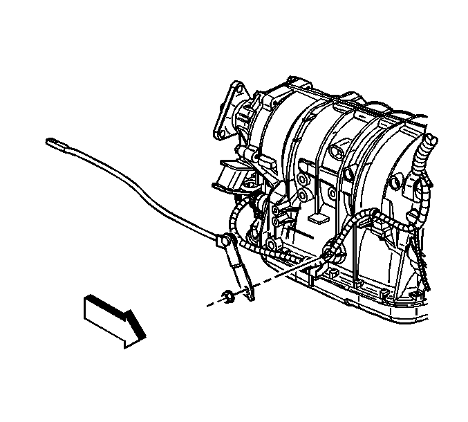
- Disconnect the shift linkage from the transmission. The linkage may be on the right or left side of the transmission depending on the application. Refer
to
Shift Control Linkage Replacement
.

- Disconnect the transmission wiring harness connector from the transmission by rotating the locking latch counterclockwise.
- Disconnect the wiring harness retainers from the transmission, and position the wiring harness aside.
- Remove the transmission fluid cooler lines from the plastic cooler line retainer bracket.
- Place an oil drain pan under the transmission fluid cooler pipes.

- Remove the transmission fluid cooler pipes from the transmission, and position aside. Refer to
Transmission Fluid Cooler Pipe Replacement - Rear
.
- Remove and discard the O-rings. Do NOT reuse the O-rings.
- Plug the open outlet ports to prevent fluid loss and contamination.
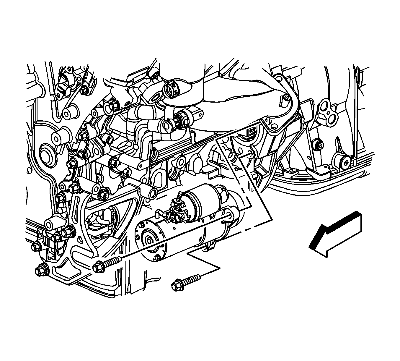
- Remove the starter motor to gain access to the torque converter bolts. Refer to
Starter Motor Replacement
.
- Mark the torque converter to flexplate/flywheel orientation to ensure proper realignment.
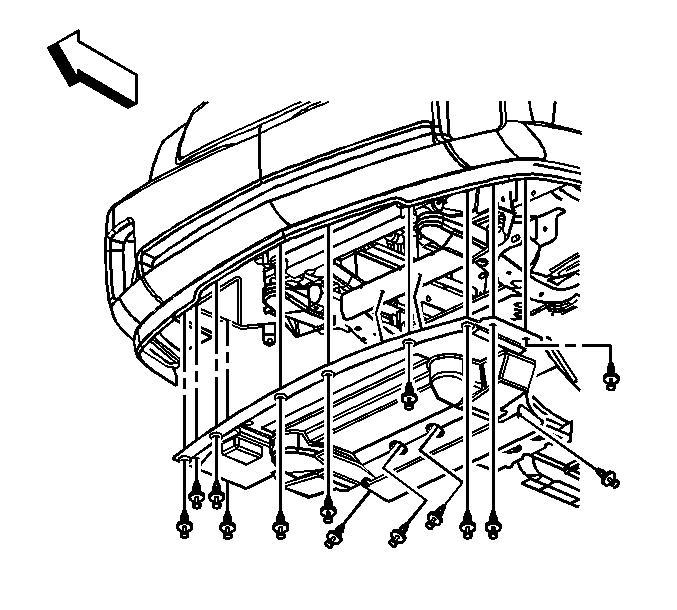
- Remove the front air deflector. Refer to
Front Air Deflector Replacement
.
- Repeat the following steps for all 3 torque converter bolts:
| 18.1. | Rotate the harmonic balancer center bolt or fan adapter, depending on the application, clockwise ONLY, in order to align the torque converter bolt with the access hole. |
| 18.2. | Remove and discard the torque converter bolt. The bolt is self locking and is NOT reusable. |

- Remove the front differential heat shield and bracket if equipped. Refer to
Shield Replacement
.

Important: Be careful to NOT allow the front differential drive pinion flange, if equipped, to come in contract with power steering rack while lowering the transmission.
- Using the transmission jack. Lower the engine and transmission assembly only enough to gain access to the upper 2 transmission mounting bolts.
- Position the engine wiring harness out of the way.
- Remove the upper 2 bolts.

- Using the transmission jack. Raise the engine and transmission assembly to the normal position.
- Place a support stand under the rear of the engine oil pan to keep the engine level while removing the transmission.

- Remove the lower 8 transmission mounting bolts.
- Pull the transmission free from the engine dowels (1).
Important: Ensure clearance is maintained between the transmission and the following:
| • | The starter drive nose cone |
| • | The catalytic converters |
- Carefully lower the transmission from the vehicle.
- Flush the transmission oil cooler. Refer to
Transmission Fluid Cooler Flushing and Flow Test
.
- If the transmission is being replaced and it is a rear wheel drive vehicle, transfer the drive flange from the old unit to the new unit. Refer to
Drive Flange and Seal Replacement
.
Installation Procedure
Important: Ensure clearance is maintained between the transmission and the following:
| • | The catalytic converters |
- Using the transmission jack, carefully raise the transmission to meet the engine.

- Align the transmission with the engine dowels (1).
Notice: Refer to Fastener Notice in the Preface section.
- Install the lower 8 transmission mounting bolts.
Tighten
| • | Tighten the M10 x 1.5 bolts to 50 N·m (37 lb ft). |
| • | Tighten the M12 x 1.75 bolts to 75 N·m (55 lb ft). |
- Remove the support stand from under the engine oil pan.

Important: Be careful to NOT allow the front differential drive pinion flange, if equipped, to come in contract with power steering rack while lowering the transmission.
- Using the transmission jack. Lower the engine and transmission assembly only enough to gain access to the upper transmission bolt locations.
- Install the upper transmission mounting bolts.
Tighten
| • | Tighten the M10 x 1.5 bolts to 50 N·m (37 lb ft). |
| • | Tighten the M12 x 1.75 bolts to 75 N·m (55 lb ft). |
- Position the engine wiring harness to the original location.
- Install the transfer case if equipped. Refer to
Transfer Case Assembly Replacement
.
- Align the torque converter to flexplate/flywheel orientation marks made during the removal procedure.
Important: Torque converter bolts are self locking and must be replaced with NEW torque converter bolts every time the bolts are removed.
- Complete the following steps for all 3 torque converter bolts:
| 10.1. | Rotate the harmonic balancer center bolt or the fan adapter, depending on the application, clockwise ONLY, in order to align the torque converter bolt holes in the flexplate/flywheel with the access hole in the engine block. |
| 10.2. | To aid in alignment of the torque converter to the flexplate/flywheel. Install all 3 NEW torque converter bolts before fully tightening. |
Tighten
Tighten the torque converter bolts to 63 N·m (46 lb ft).

- Install the starter motor. Refer to
Starter Motor Replacement
.

- Install the front air deflector. Refer to
Front Air Deflector Replacement
.

- Place NEW O-rings over the transmission fluid cooler pipes.
- Install the transmission fluid cooler pipes to the transmission. Refer to
Transmission Fluid Cooler Pipe Replacement - Rear
.
- Clip the transmission fluid cooler lines into the plastic cooler line retainer bracket.

- Install the front differential heat shield and bracket, if equipped. Refer to
Shield Replacement
.

- Connect the wiring harness retainers to the transmission.
- Connect the transmission wiring harness connector (1) to the transmission by rotating the locking latch clockwise.

- Connect the shift linkage to the transmission. Refer to
Shift Control Linkage Replacement
.
- Install the rear propeller shaft. Refer to
Rear Propeller Shaft Replacement
.
- Install the exhaust system. Refer to
Exhaust System Replacement
.
- Install the thermostat housing. Refer to
Engine Coolant Thermostat Housing Replacement
.
- Connect the negative battery cable. Refer to
Battery Negative Cable Disconnection and Connection
.
- Check the transmission fluid level and fill if necessary. Refer to
Transmission Fluid Check
.
- Adjust the shift control linkage. Refer to
Shift Control Linkage Adjustment
.
- Lower the vehicle.
Transmission Final Test and Inspection
Complete the following procedure after the transmission is installed in the vehicle:
- With the ignition OFF or disconnected, crank the engine several times. Listen for any unusual noises or evidence that any parts are binding.
- Start the engine and listen for abnormal conditions.
- While the engine continues to idle, raise and support the vehicle. Refer to
Lifting and Jacking the Vehicle
.
- Inspect for fluid leaks while the engine is idling.
- Perform a final inspection for the proper fluid level.
- Lower the vehicle.
Important: It is recommended that transmission adaptive pressure (TAP) information be reset.
Resetting the TAP values using a scan tool will erase all learned values in all cells. As a result, The ECM, PCM or TCM will
need to relearn TAP values. Transmission performance may be affected as new TAP values are learned.
- Reset the TAP values. Refer to
Transmission Adaptive Functions
.
- Road test the vehicle.


