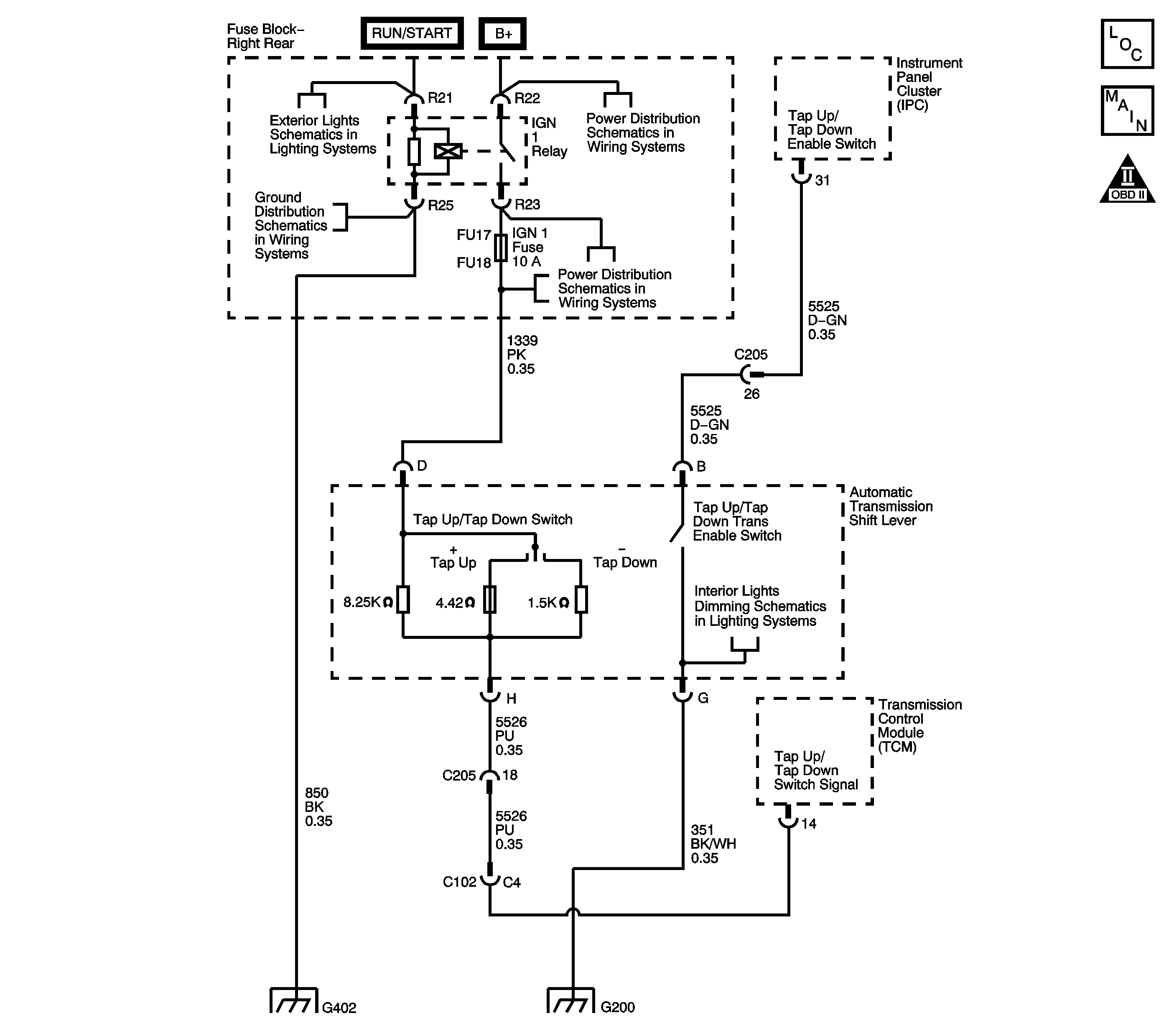
Circuit Description
The TAP Shift system allows the driver to manually shift gears by using the TAP Shift switches located on the automatic transmission shift lever. Pushing the shifter handle forward will command an upshift and pulling the shifter handle back will command a downshift. The TAP Shift system is activated when the gear selector is in the manual (M) position and is deactivated in all other positions.
Step | Action | Value(s) | Yes | No |
|---|---|---|---|---|
1 |
Are DTC's P0815, P0816, P0826 or P1876 set? | -- | Go to Step 2 | |
2 |
Does the scan tool Driver Shift Control parameter display Inactive? | -- | Go to Step 3 | Go to Step 8 |
3 |
Does the scan tool Driver Shift Control parameter display Active? | -- | Go to Step 6 | Go to Step 4 |
4 | Using the J 39200 DMM and the J 35616 GM terminal test kit, measure the voltage between the TAP Up/TAP Down enable signal circuit and a known good ground at the AT shift lever connector. Does the voltage measure near the specified voltage? | 12 V | Go to Step 5 | Go to Step 9 |
5 | Using the J 39200 DMM and the J 35616 GM terminal test kit, measure the voltage between the TAP Up/TAP Down enable signal circuit and the TAP Up/TAP Down ground circuit at the AT shift lever connector. Does the voltage measure near the specified voltage? | 12 V | Go to Step 11 | Go to Step 10 |
6 |
Does the Driver Shift Request parameter display upshift? | -- | Go to Step 7 | Go to Step 11 |
7 | While observing the scan tool, move the AT shift lever in the downshift position. Does the Driver Shift Request parameter display downshift? | -- | Go to Testing for Intermittent Conditions and Poor Connections | Go to Step 11 |
8 | Test the Driver Shift Control enable signal circuit for a short to ground. Refer to Testing for Short to Ground and Wiring Repairs . Did you find and correct the condition? | -- | Go to Step 13 | Go to Step 12 |
9 | Test the Driver Shift Control enable signal circuit for an open. Refer to Testing for Continuity and Wiring Repairs . Did you find and correct the condition? | -- | Go to Step 13 | Go to Step 12 |
10 | Test the Driver Shift Control ground circuit for an open. Refer to Testing for Continuity and Wiring Repairs . Did you find and correct the condition? | -- | Go to Step 13 | -- |
11 | Replace the floor shift control. Refer to Transmission Control Replacement . Did you complete the replacement? | -- | Go to Step 13 | -- |
12 | Replace the instrument panel cluster (IPC). Refer to Instrument Cluster Replacement . Did you complete the replacement? | -- | Go to Step 13 | -- |
13 | Perform the following procedure in order to verify the repair:
Do the Driver Shift Control and the Driver Shift Request parameters indicate the proper display? | -- | System OK | Go to Step 1 |
