GM Service Manual Online
For 1990-2009 cars only
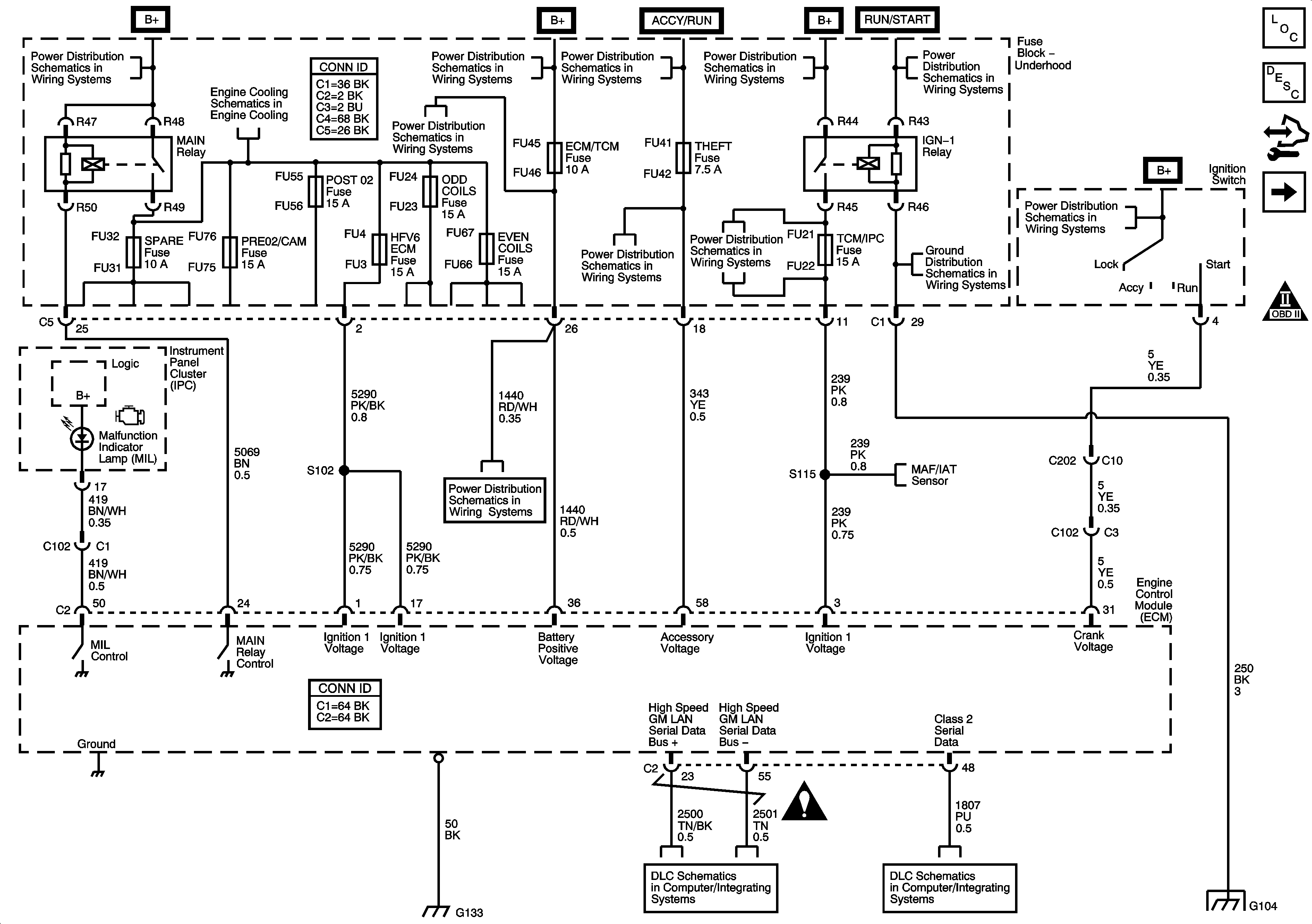
Figure 1:

Module Power, Ground, Serial Data and MIL

Object Number: 1616206  Size: FS
Master Electrical Component List
Engine Control Module Description
Control Module References
Engine Data Sensors-5 Volt Reference
Engine Controls Schematic Icons
Fuse Block Underhood B+ Bus
Cooling Fans
Fuse Block Underhood B+ Bus
RIM and THEFT Fuses and Ignition Switch 2 of 2
Fuse Block Underhood B+ Bus
ABS, STARTER RLY, STRG CTLS, TCM/IPC, AND WASH NOZ FUSES
RIM and THEFT Fuses and Ignition Switch 2 of 2
G104
IGN SW Fuse and Ignition Switch 1 of 2
Engine Data Sensors-Pressure, Temp, MAF, VSS and Extended Travel Brake Switch
Power, Ground, GMLAN and Key Word 2000 Serial Data
Engine Controls Schematic Icons
Class 2 Serial Data 1 of 2
G104
Figure 2:

Engine Data Sensors - 5-Volt Reference


Object Number: 1616208  Size: FS
Master Electrical Component List
Engine Control Module Description
Control Module References
Engine Data Sensors-Low Reference
Module Power, Ground, Serial Data and MIL
Engine Controls Schematic Icons
Figure 3:

Engine Data Sensors - Low Reference


Object Number: 1616210  Size: FS
Master Electrical Component List
Engine Control Module Description
Control Module References
Engine Data Sensors-Pressure, Temp, MAF, VSS and Extended Travel Brake Switch
Engine Data Sensors-5 Volt Reference
Engine Controls Schematic Icons
Figure 4:

Engine Data Sensors - Pressure, Temperature, MAF, VSS, and Extended Travel Brake Switch


Object Number: 1616212  Size: FS
Master Electrical Component List
Air Intake System Description
Control Module References
Engine Data Sensors-Oxygen Sensors
Engine Data Sensors-Low Reference
Engine Controls Schematic Icons
RIM and THEFT Fuses and Ignition Switch 2 of 2
G104
Fuse Block Underhood B+ Bus
ABS, STARTER RLY, STRG CTLS, TCM/IPC, AND WASH NOZ FUSES
Module Power, Ground, Serial Data and MIL
Gages
Engine Data Sensors-5 Volt Reference
Engine Data Sensors-Low Reference
G104
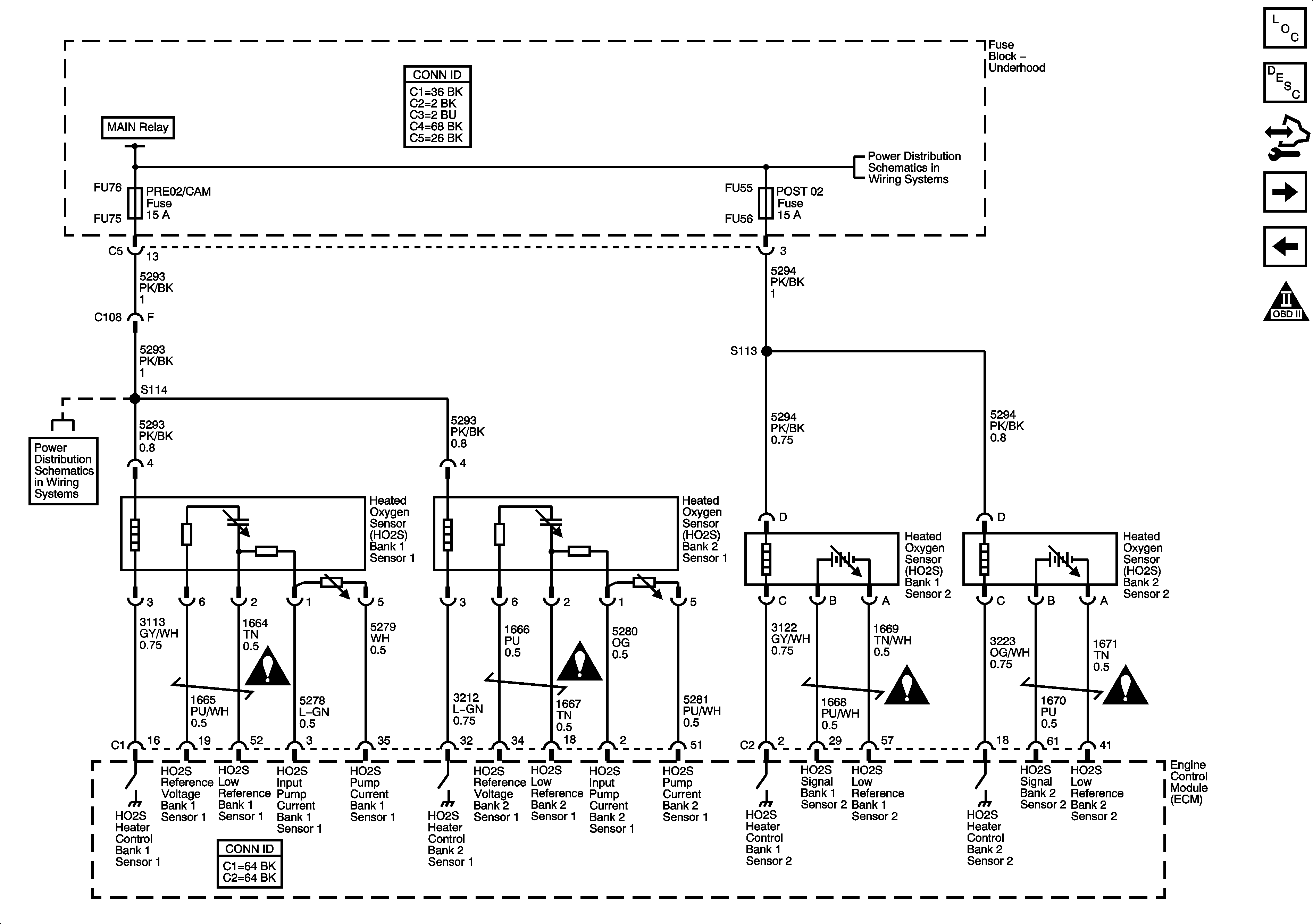
Figure 5:

Engine Data Sensors - Oxygen Sensors


Object Number: 1616213  Size: FS
Master Electrical Component List
Engine Control Module Description
Control Module References
Engine Data Sensors-Throttle Actuator Controls
Engine Data Sensors-Pressure, Temp, MAF, VSS and Extended Travel Brake Switch
Engine Controls Schematic Icons
Cooling Fans
Fuse Block Underhood B+ Bus
06 ESUV-HFVG, PRE 02/CAM, and V8 ECM Fuses
Engine Controls Schematic Icons
Figure 6:

Engine Data Sensors - Throttle Actuator Controls


Object Number: 1616214  Size: FS
Master Electrical Component List
Throttle Actuator Control (TAC) System Description
Control Module References
Ignition Controls-Bank 1 Ignition Coils
Engine Data Sensors-Oxygen Sensors
Engine Controls Schematic Icons
Figure 7:

Ignition Controls - Bank 1 Ignition Controls


Object Number: 1616215  Size: FS
Master Electrical Component List
Electronic Ignition (EI) System Description
Control Module References
Ignition Controls-Bank 2 Ignition Coils
Engine Data Sensors-Throttle Actuator Controls
Engine Controls Schematic Icons
EVEN COILS, ODD COILS, and POST 02 Fuses
Cooling Fans
EVEN COILS, ODD COILS, and POST 02 Fuses
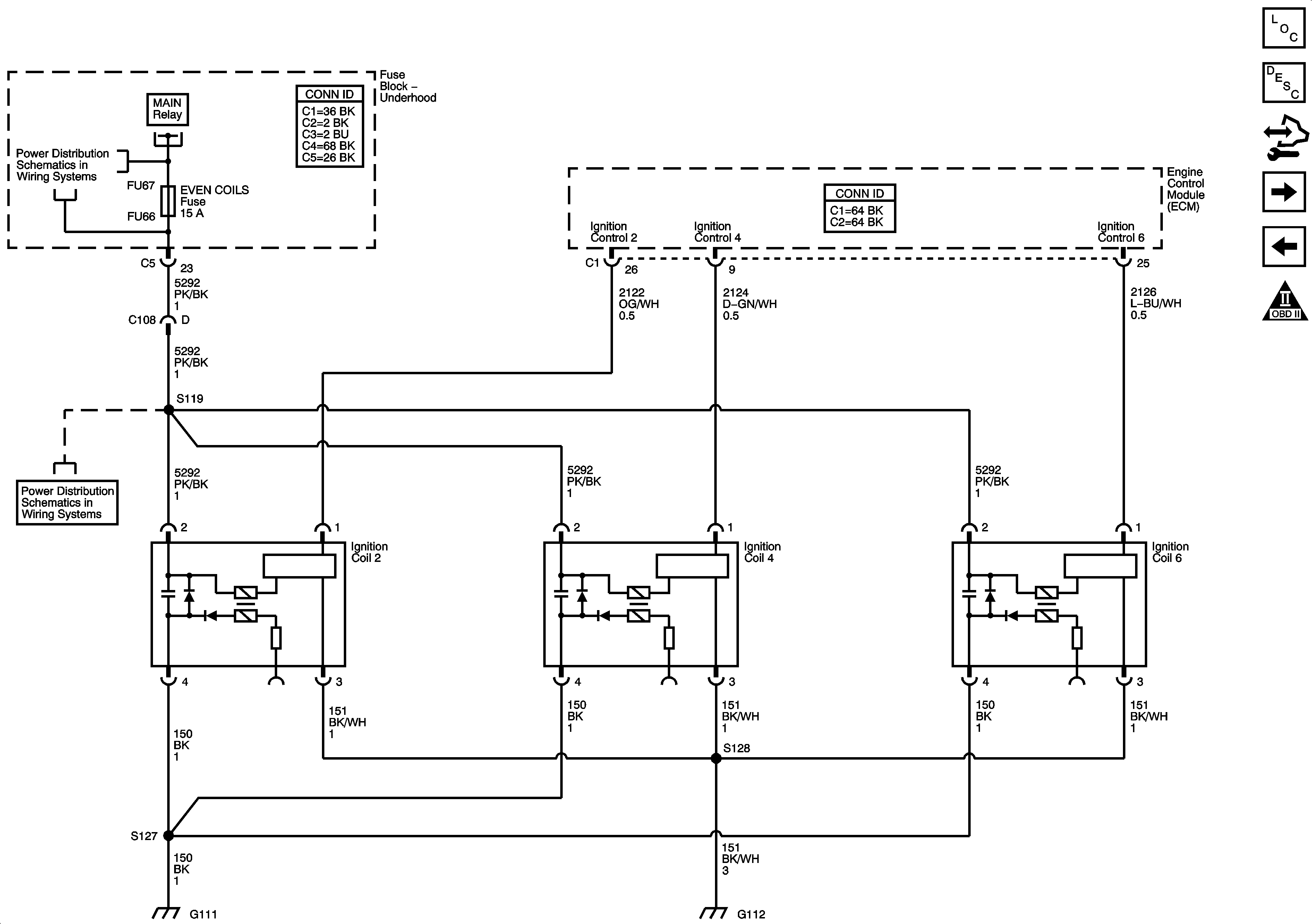
Figure 8:

Ignition Controls - Bank 2 Ignition Coils

Object Number: 1616216  Size: FS
Master Electrical Component List
Electronic Ignition (EI) System Description
Control Module References
Ignition Controls-CMP Sensors and Solenoids
Ignition Controls-Bank 1 Ignition Coils
Engine Controls Schematic Icons
EVEN COILS, ODD COILS, and POST 02 Fuses
Cooling Fans
EVEN COILS, ODD COILS, and POST 02 Fuses
Figure 9:

Ignition Controls - CMP Sensors and Solenoids


Object Number: 1616218  Size: FS
Master Electrical Component List
Camshaft Actuator System Description
Control Module References
Ignition Controls-Engine Speed, CKP and Knock Sensors
Ignition Controls-Bank 2 Ignition Coils
Engine Controls Schematic Icons
06 ESUV-HFVG, PRE 02/CAM, and V8 ECM Fuses
Engine Data Sensors-Low Reference
Figure 10:

Ignition Controls - Engine Speed, CKP and Knock Sensors


Object Number: 1616220  Size: FS
Master Electrical Component List
Knock Sensor (KS) System Description
Control Module References
Fuel Controls-Fuel Pump and Injectors
Ignition Controls-CMP Sensors and Solenoids
Engine Controls Schematic Icons
Gages
Engine Controls Schematic Icons
Figure 11:

Fuel Controls - Fuel Pump and Injectors


Object Number: 1616221  Size: FS
Master Electrical Component List
Fuel System Description
Control Module References
Fuel Controls-EVAP Controls
Ignition Controls-Engine Speed, CKP and Knock Sensors
Engine Controls Schematic Icons
Cooling Fans
EVEN COILS, ODD COILS, and POST 02 Fuses
Fuse Block Right Rear B+ Bus
G402 1 of 2
G401 1 of 2
Gages
Figure 12:

Fuel Controls - EVAP Controls


Object Number: 1616222  Size: FS
Master Electrical Component List
Evaporative Emission Control System Description
Control Module References
Controlled/Monitored Subsystem References
Fuel Controls-Fuel Pump and Injectors
Engine Controls Schematic Icons
Cooling Fans
06 ESUV-HFVG, PRE 02/CAM, and V8 ECM Fuses
Engine Data Sensors-Low Reference
Engine Data Sensors-5 Volt Reference
Engine Data Sensors-Low Reference
Fuse Block Right Rear B+ Bus
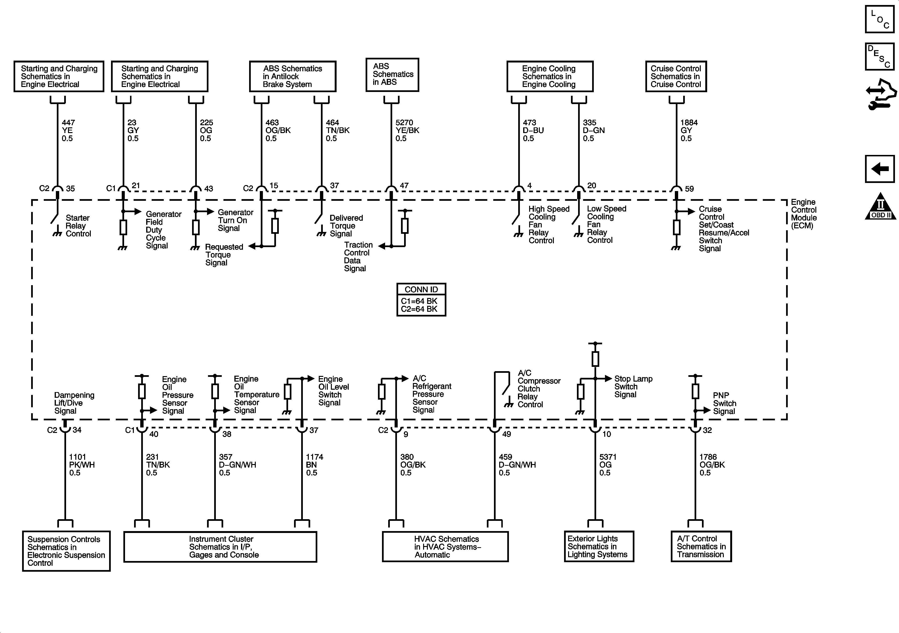
Figure 13:

Controlled/Monitored Subsystem References


Object Number: 1616223  Size: FS
Master Electrical Component List
Engine Control Module Description
Control Module References
Fuel Controls-EVAP Controls
Engine Controls Schematic Icons
Starting System
Charging System
Indicator, Traction Control, and Brake Pedal Position
Cooling Fans
Cruise Control Schematics
Power, Ground, Serial Data and Controls
Indicators
Serial Data and A/C Compressor Controls
Tail Lamps and Stop Lamps-Domestic
Power, Ground, Serial Data and Switches