Brake Pedal Assembly Replacement Before VIN 40108010
Removal Procedure
- Remove the vacuum brake booster. Refer to Power Vacuum Brake Booster Replacement.
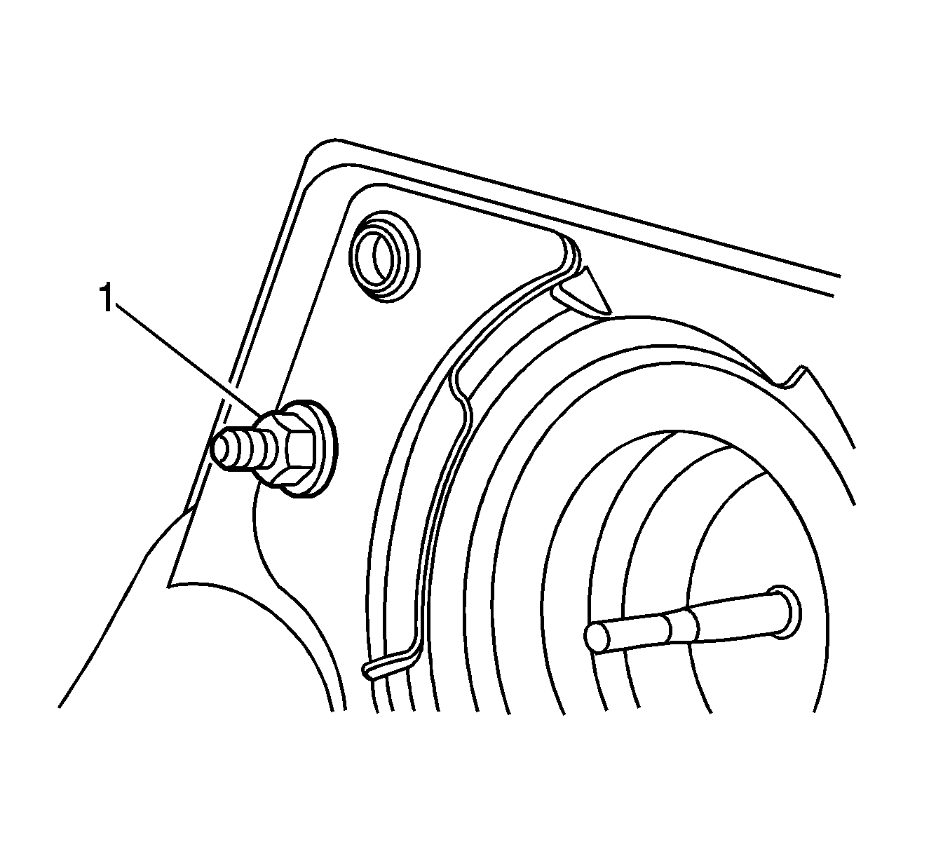
- Remove the steering column support bracket nut (1).
- Without disconnecting the park brake cable, remove and position aside the park brake pedal assembly. Refer to Parking Brake Lever Pedal Assembly Replacement.
- Without disconnecting the steering column from the intermediate shaft, lower the steering column assembly and support the column. Refer to Steering Column Replacement.
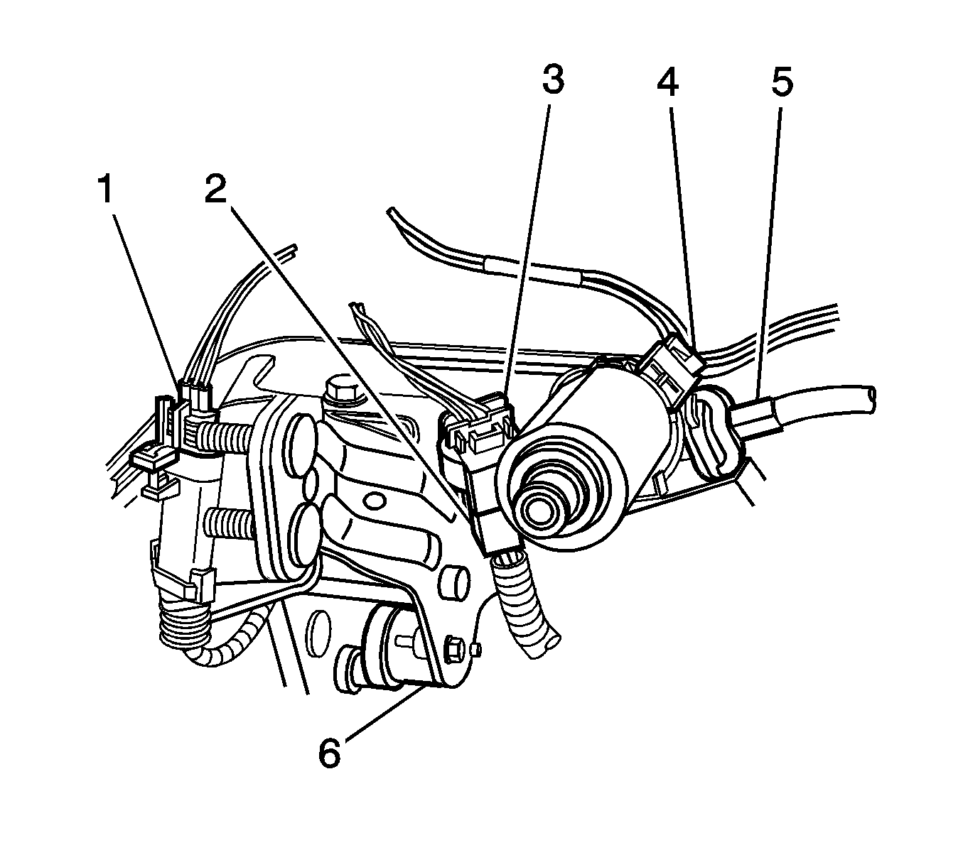
- Disconnect the electrical connector from the brake apply sensor (BAS) (6).
- Disconnect the electrical connector (4) from the adjustable brake pedal motor.
- Disconnect the electrical connector (1) from the adjustable brake pedal position sensor.
- Disconnect the adjustable accelerator pedal wiring harness (2) from the adjustable brake pedal bracket.
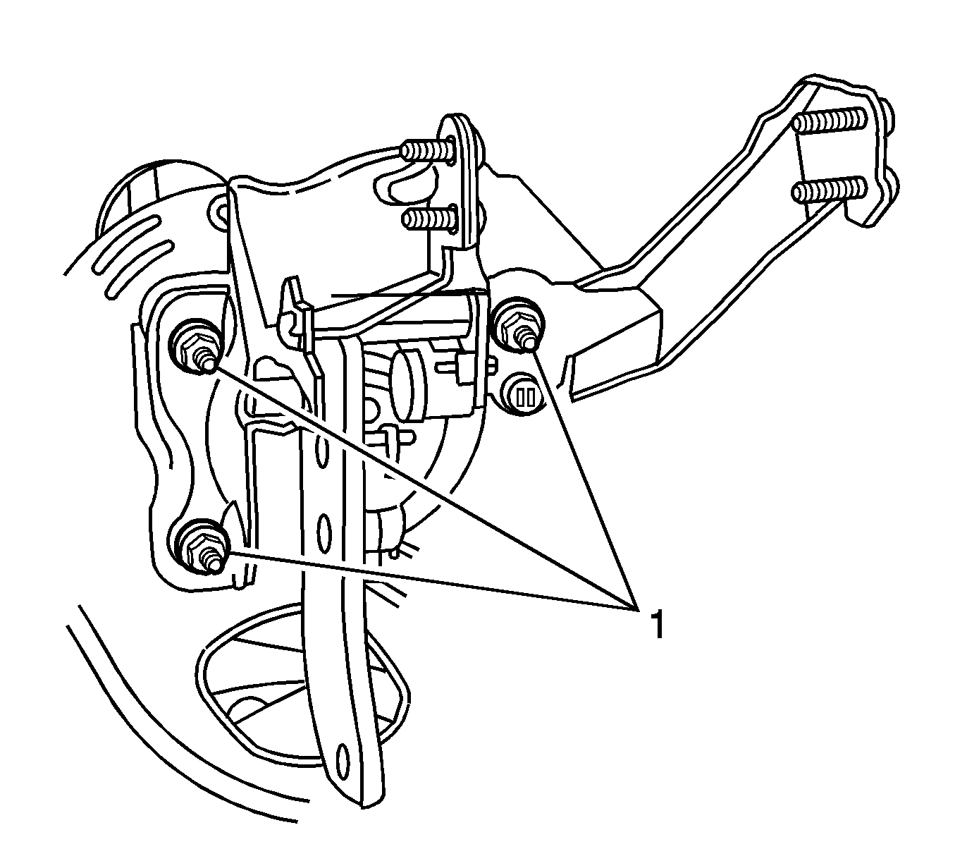
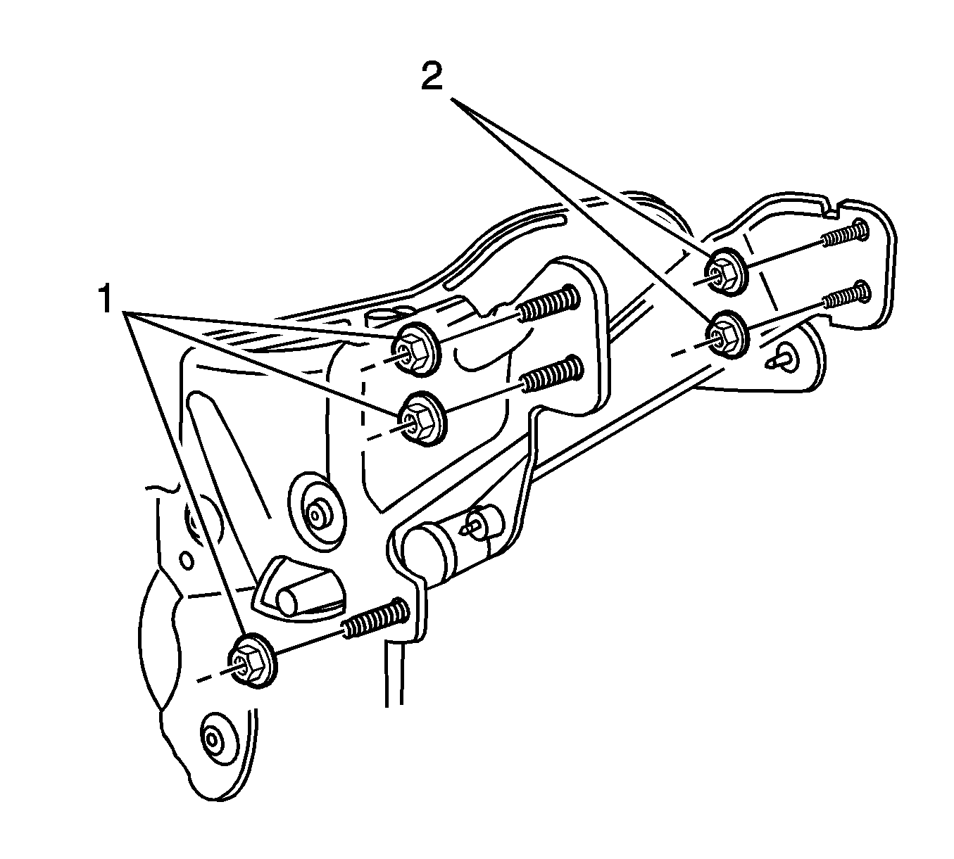
- Remove the 3 brake pedal assembly nuts (1).
- Remove the 2 steering column support bracket nuts (2).
- Remove the 3 brake pedal assembly nuts (1).
- Remove the I/P carrier. Refer to Instrument Panel Carrier Replacement.
- Remove the steering column support bracket (1).
- Carefully squeeze the collar of the adjustable accelerator pedal cable and disconnect the accelerator pedal cable from the adjustable brake pedal motor.
- Remove the brake pedal assembly from the vehicle.
Installation Procedure
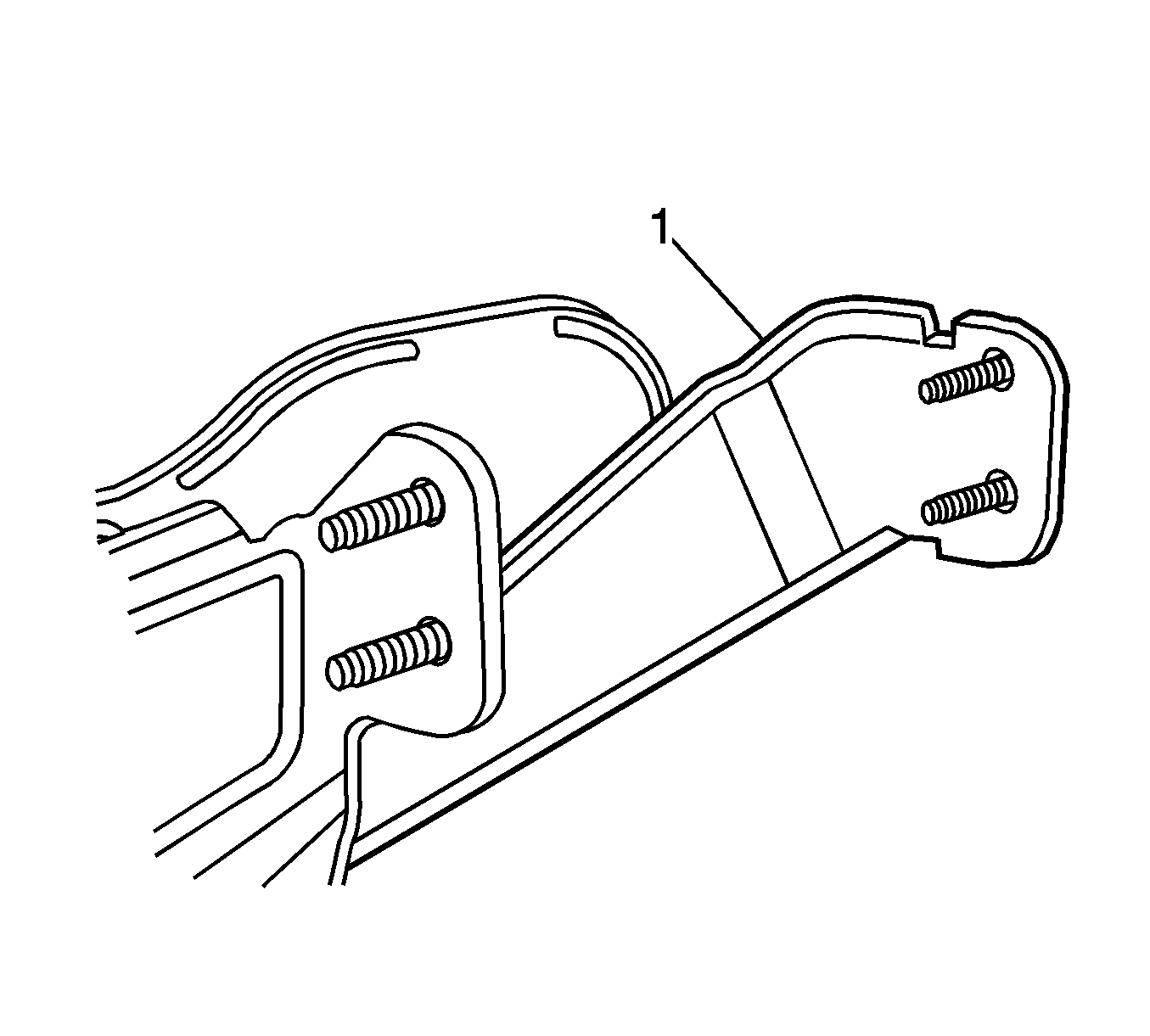
- Synchronize the accelerator pedal to the full forward position. Using an adjustable wrench on the adjustable pedal cable end, slowly rotate the cable to move the pedal to the full forward, front of vehicle position.
- Remove the adjustable wrench from the cable.
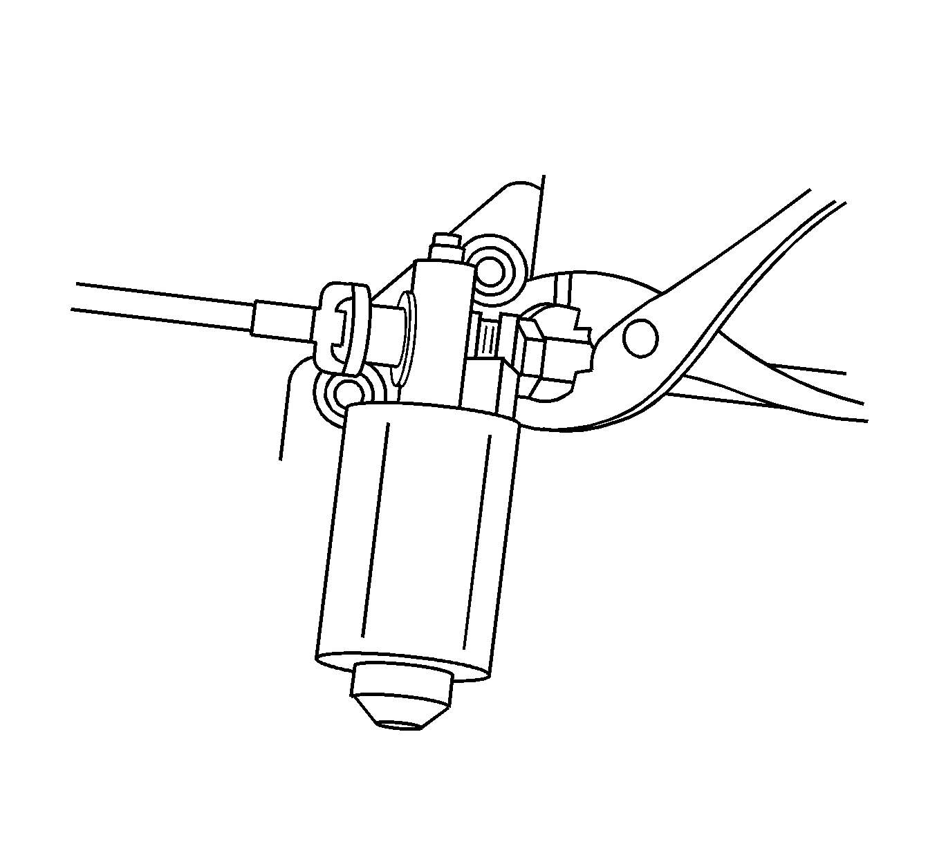
- Synchronize the brake pedal to the full forward position. Install a square drive tool into the adjustable brake pedal motor and carefully rotate the motor to move the pedal to the full forward, front of vehicle position.
- Remove the square drive tool.
- Install the adjustable brake pedal assembly to the vehicle.
- Carefully connect the adjustable accelerator pedal cable (5) to the adjustable brake pedal motor. Ensure the adjustable brake pedal cable retainer is locked into place by carefully pulling on the cable.
- Install the steering column support bracket (1).
- Install the I/P carrier. Refer to Instrument Panel Carrier Replacement.
- Install the 3 brake pedal assembly nuts (1).
- Install the 3 brake pedal assembly nuts (1).
- Install the steering column support bracket nut (1).
- Install the 2 steering column support bracket nuts (2).
- Connect the electrical connector to the adjustable brake pedal position sensor (1).
- Connect the adjustable accelerator pedal electrical harness (2) to the adjustable brake pedal bracket.
- Connect the electrical connector (4) to the adjustable brake pedal motor.
- Connect the electrical connector to the BAS (6).
- Position and secure the steering column assembly. Refer to Steering Column Replacement.
- Position and secure the park brake pedal assembly. Refer to Parking Brake Lever Pedal Assembly Replacement.
- Install the vacuum brake booster. Refer to Power Vacuum Brake Booster Replacement.
- Calibrate the brake pedal position sensor. Refer to Brake Pedal Position Sensor Replacement.
Important: Ensure the adjustable accelerator pedal and adjustable brake pedal are synchronized in the full forward, front of vehicle position.
Important: Do not exceed 0.5 N·m (4.43 lb in) of torque.


Notice: Refer to Fastener Notice in the Preface section.

Tighten
Tighten the nuts to 25 N·m (18 lb ft).

Tighten
Tighten the nuts to 25 N·m (18 lb ft).

Tighten
Tighten the nut to 25 N·m (18 lb ft).

Tighten
Tighten the nuts to 25 N·m (18 lb ft).

Brake Pedal Assembly Replacement After VIN 40108010
Removal Procedure
- Remove the vacuum brake booster. Refer to Power Vacuum Brake Booster Replacement .
- Remove the steering column support bracket nut (1).
- Without disconnecting the park brake cable, remove and position aside the park brake pedal assembly. Refer to Parking Brake Lever Pedal Assembly Replacement .
- Without disconnecting the steering column from the intermediate shaft, lower the steering column assembly and support the column. Refer to Steering Column Replacement .
- Disconnect the electrical connector from the brake apply sensor (BAS) (6).
- Disconnect the electrical connector (4) from the adjustable brake pedal motor.
- Disconnect the electrical connector (1) from the adjustable brake pedal position sensor.
- Disconnect the adjustable accelerator pedal wiring harness (2) from the adjustable brake pedal bracket.
- Remove the 3 brake pedal assembly nuts (1).
- Remove the 3 brake pedal assembly nuts (1).
- Remove the 2 steering column support bracket nuts (2).
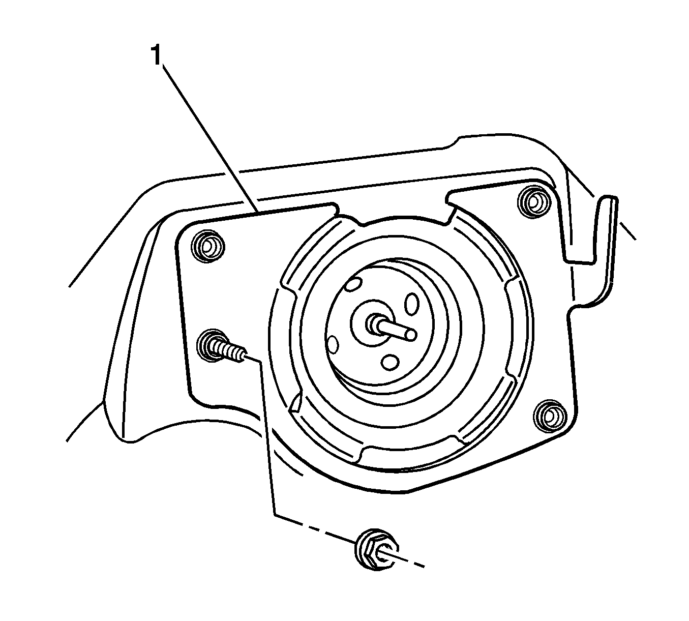
- Remove the power vacuum brake booster mounting plate (1).
- Remove the steering column support bracket (1).
- Carefully squeeze the collar of the adjustable accelerator pedal cable and disconnect the accelerator pedal cable from the adjustable brake pedal motor.
- Remove the brake pedal assembly from the vehicle.




Installation Procedure
- Synchronize the accelerator pedal to the full forward position. Using an adjustable wrench on the adjustable pedal cable end, slowly rotate the cable to move the pedal to the full forward, front of vehicle position.
- Remove the adjustable wrench from the cable.
- Synchronize the brake pedal to the full forward position. Install a square drive tool into the adjustable brake pedal motor and carefully rotate the motor to move the pedal to the full forward, front of vehicle position.
- Remove the square drive tool.
- Install the adjustable brake pedal assembly to the vehicle.
- Carefully connect the adjustable accelerator pedal cable (5) to the adjustable brake pedal motor. Ensure the adjustable brake pedal cable retainer is locked into place by carefully pulling on the cable.
- Install the steering column support bracket (1).
- Install the power vacuum brake booster mounting plate (1).
- Install the 3 brake pedal assembly nuts (1).
- Install the 3 brake pedal assembly nuts (1).
- Install the steering column support bracket nut (1).
- Install the 2 steering column support bracket nuts (2).
- Connect the electrical connector to the adjustable brake pedal position sensor (1).
- Connect the adjustable accelerator pedal electrical harness (2) to the adjustable brake pedal bracket.
- Connect the electrical connector (4) to the adjustable brake pedal motor.
- Connect the electrical connector to the BAS (6).
- Position and secure the steering column assembly. Refer to Steering Column Replacement .
- Position and secure the park brake pedal assembly. Refer to Parking Brake Lever Pedal Assembly Replacement .
- Install the vacuum brake booster. Refer to Power Vacuum Brake Booster Replacement .
- Calibrate the adjustable pedal system. Refer to Adjustable Pedal System Calibration .
Important: Ensure the adjustable accelerator pedal and adjustable brake pedal are synchronized in the full forward, front of vehicle position.
Important: Do not exceed 0.5 N·m (4.43 lb in) of torque.


Notice: Refer to Fastener Notice in the Preface section.

Tighten
Tighten the nuts to 25 N·m (18 lb ft).

Tighten
Tighten the nuts to 25 N·m (18 lb ft).

Tighten
Tighten the nut to 25 N·m (18 lb ft).

Tighten
Tighten the nuts to 25 N·m (18 lb ft).

