Hard Brake Pedal On Cold Start At High Altitudes (Install Auxiliary Vacuum Pump)

| Subject: | Hard Brake Pedal On Cold Start At High Altitudes (Install Auxiliary Vacuum Pump) |
| Models: | 2008 Cadillac CTS |
| with 3.6L V6 Engine (VIN 7 - RPO LY7) |
Condition
Some customers may comment on a hard brake pedal. This condition is most apparent in the first 30 second to one minute after a cold start and at high altitudes, usually between 1219-1829 m (4000-6000 ft).
Cause
This condition may be caused by low engine vacuum during warm up.
Correction
Install an auxiliary vacuum pump with installation kit following the procedure below.
- Remove the three TORX® head bolts and rotate the pump assembly counterclockwise one bolt position. Apply GM Threadlocker Medium Strength Blue, P/N 12345382 (in Canada, use P/N 10953489) or equivalent, to the three TORX® head bolts.
- Mount the pump on to the bracket using the supplied M8 bolts and nuts.
- Install the electrical harness to the pump.
- Disconnect the negative battery cable.
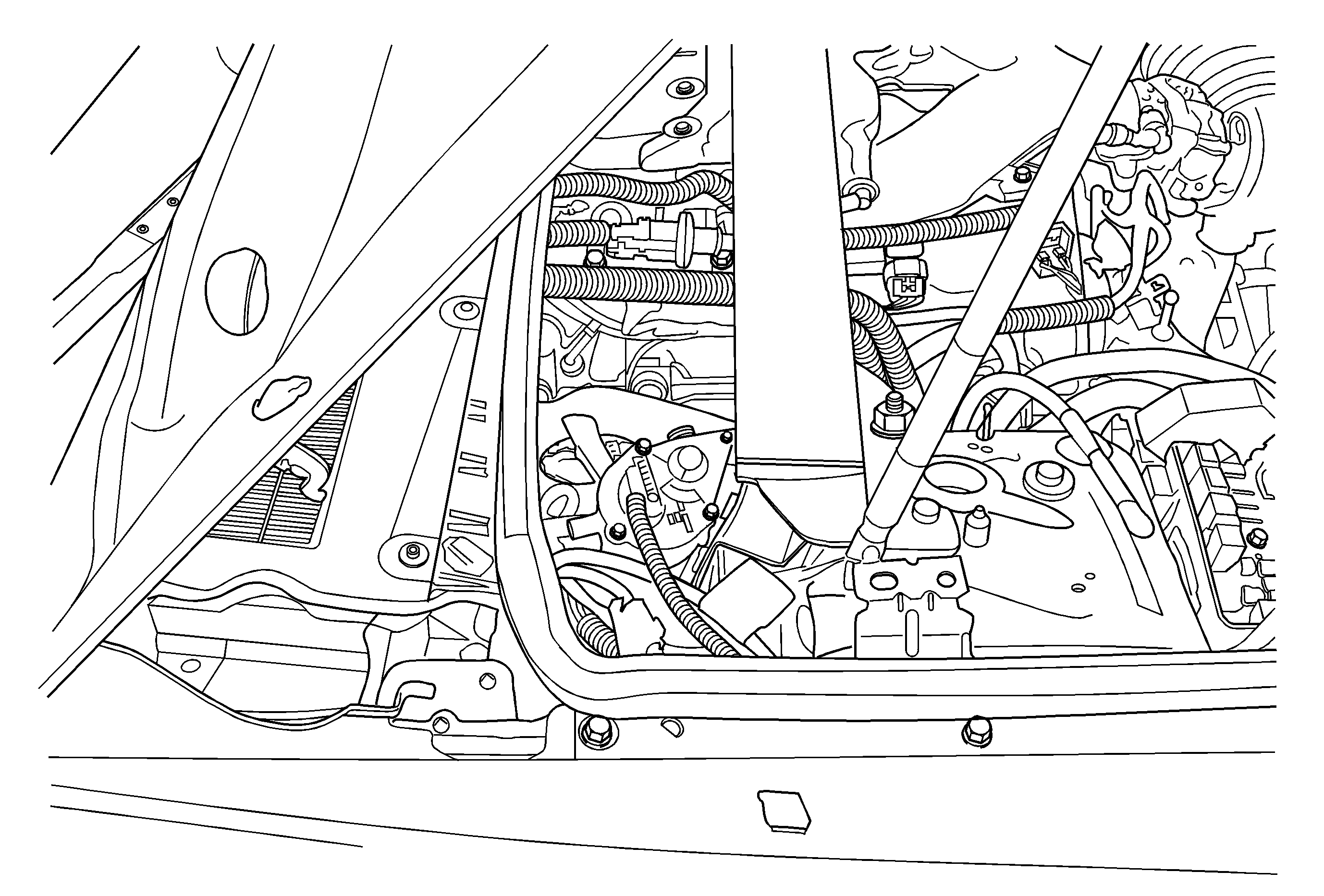
- Remove the front and rear engine covers. The rear cover is secured in place with two push pins.
- Remove the side cover.
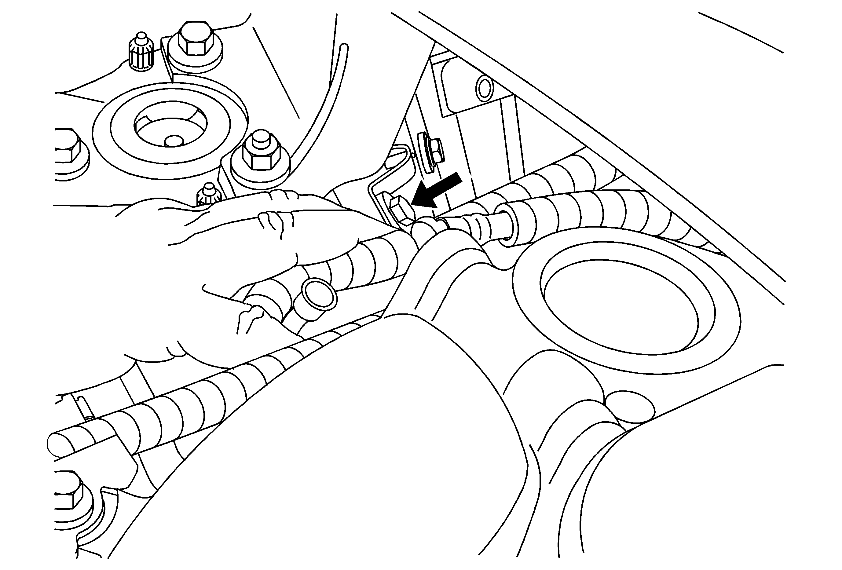
- Remove the M12 strut assembly bolt on the rear of the right strut tower.
- Mount the pump to the rear of the strut tower using the M12 strut assembly bolt and the M6 supplied with the kit.
- Remove and discard the OEM brake booster vacuum hose. Leave the check valve connected to the booster.
- Cut a length of hose 1240 mm (48-3/4 in) long of 12 mm (15/32 in) I.D. reinforced EPDM rubber vacuum hose. (This hose is not supplied with the kit.)
- Install the hose on each end.
- Install the hose to the vacuum pump outlet port that is facing toward the front of dash and position the clamp to secure the hose.
- Route the hose behind the engine and connect it to the engine vacuum port, being careful not to kink the hose. Position the clamp to secure the hose.
- Cut a length of hose 935 mm (36-3/4 in) long of 12 mm (15/32 in) I.D. reinforced EPDM rubber vacuum hose. (This hose is not supplied with the kit. )
- Install the hose on each end.
- Install the hose to the vacuum pump inlet port that is facing toward the engine and position the clamp to secure the hose.
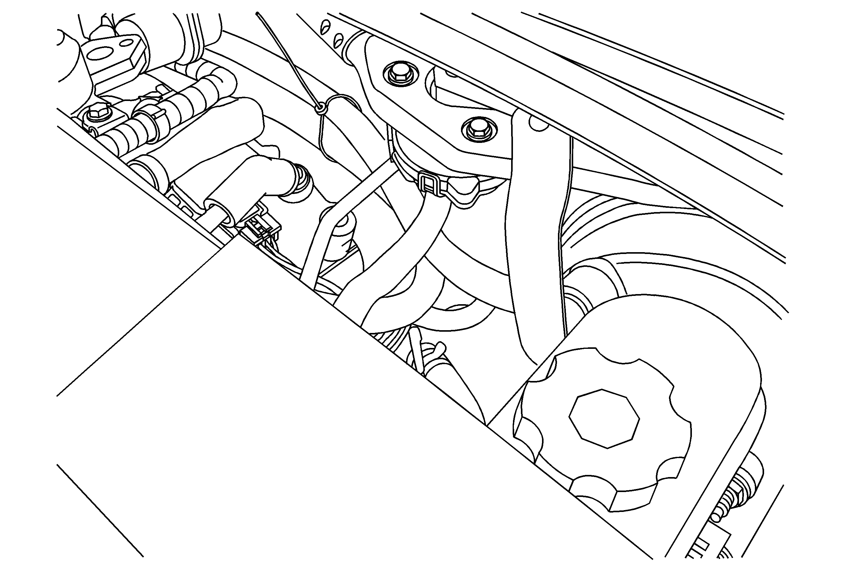
- Route the hose behind the engine and to the brake booster check valve. Position the clamp to secure the hose.
- Install a tie strap around the hoses and wiring harness.
- Reinstall the engine covers.
- Install the terminal to the wire harness. Use the SPX Kent-Moore Yazaki Connector Kit, Tray 9, Terminal 13 (7116-4111-02).
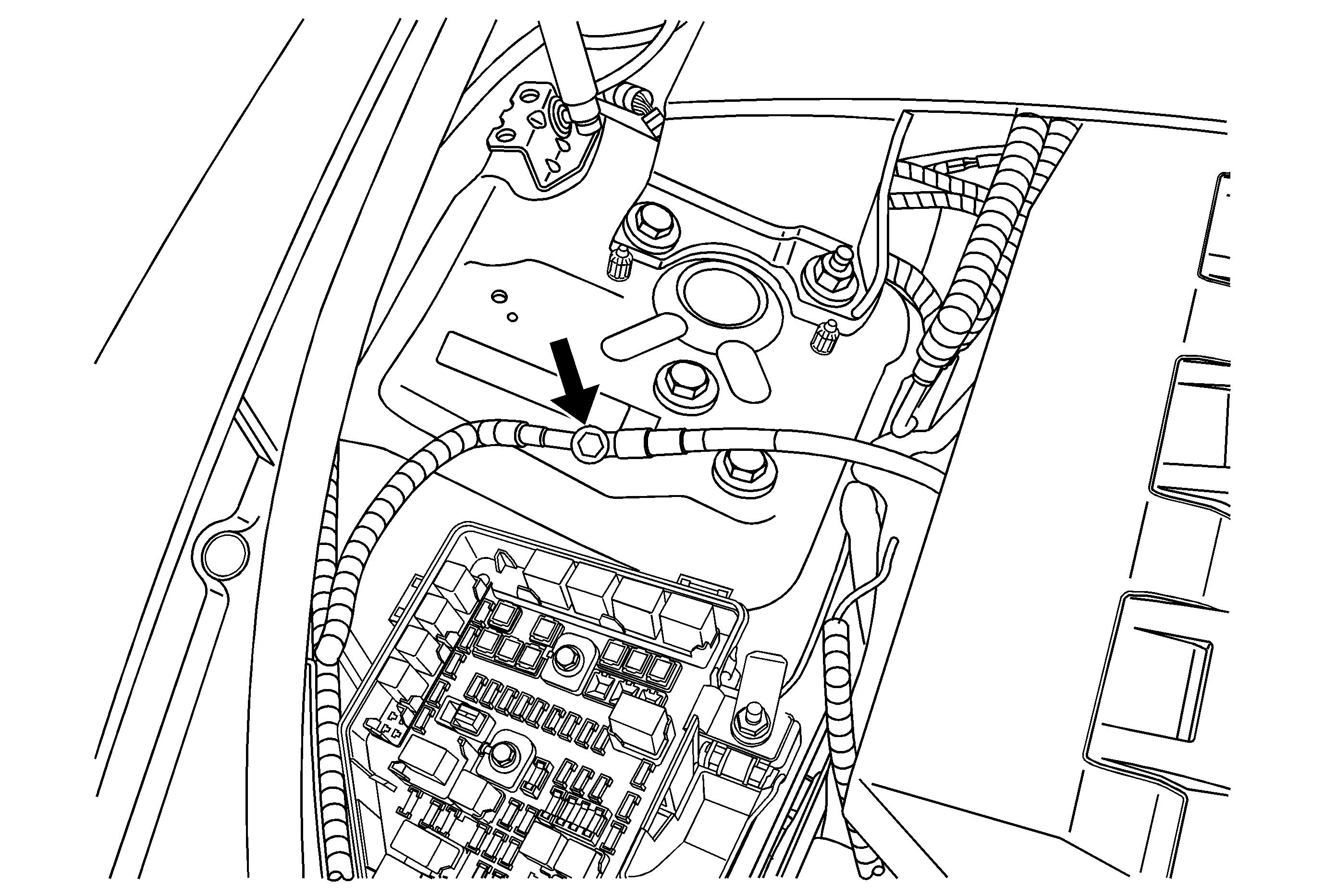
- Remove the battery ground cable extension bolt located on the right strut tower and install the ground wire for the vacuum pump.
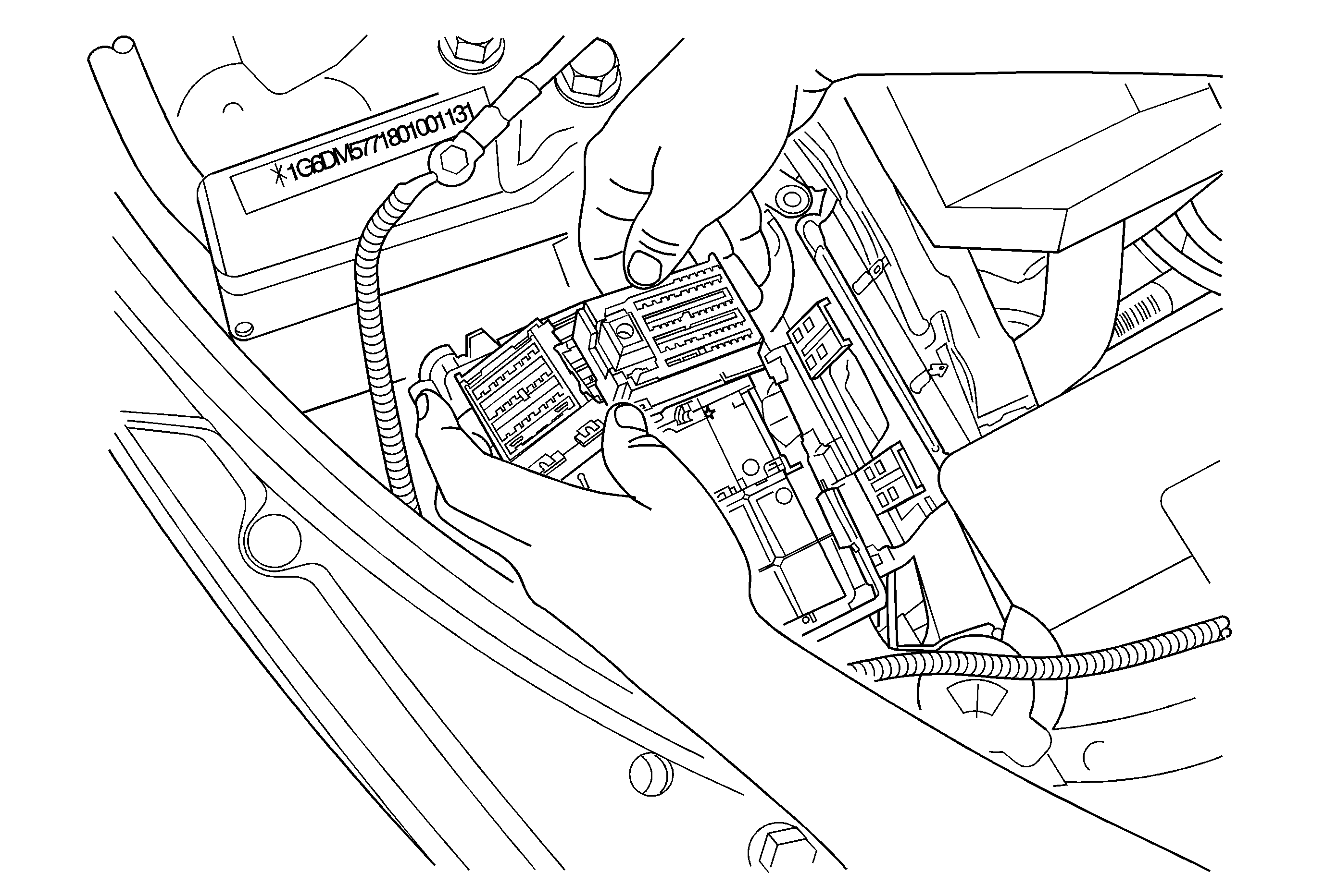
- Remove the underhood electrical center cover and disconnect the positive battery cable.
- Loosen the two bolts in the electrical center. Do not try to remove the bolts.
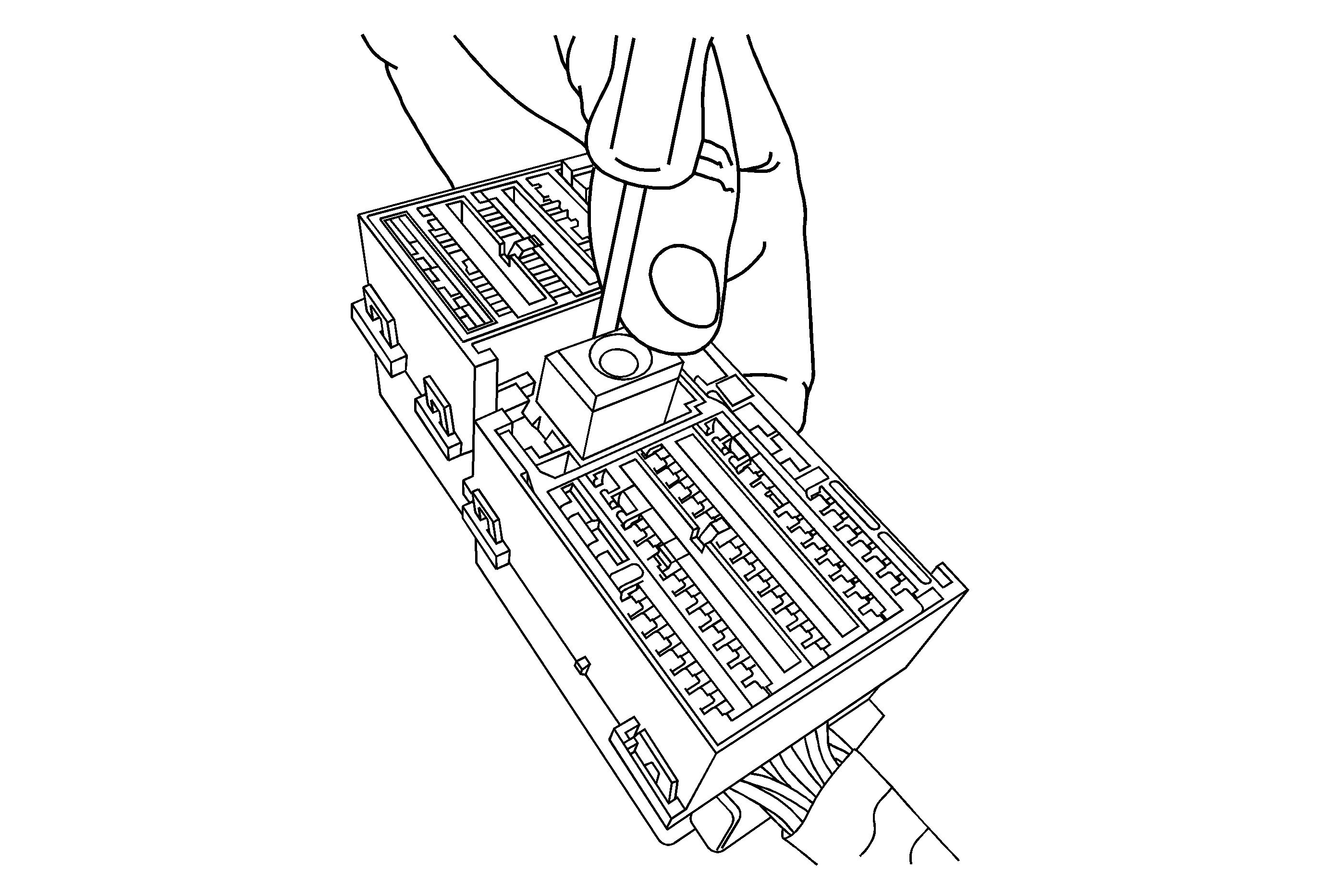
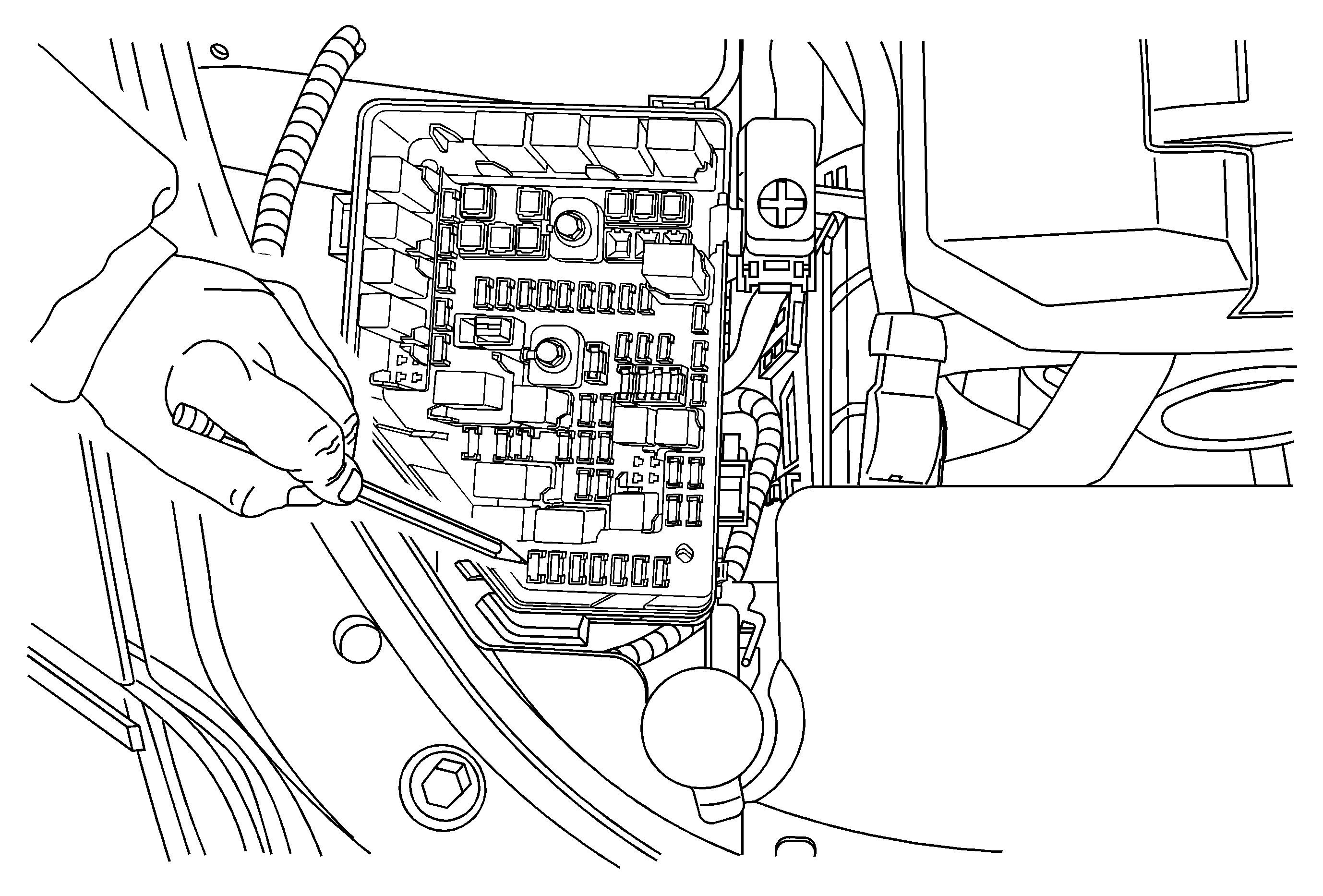
- Remove the electrical center junction block by using a hook-shaped tool to disengage the locking tabs.
- Remove the front two electrical connectors. With a small screwdriver or a pick tool, separate the connectors.
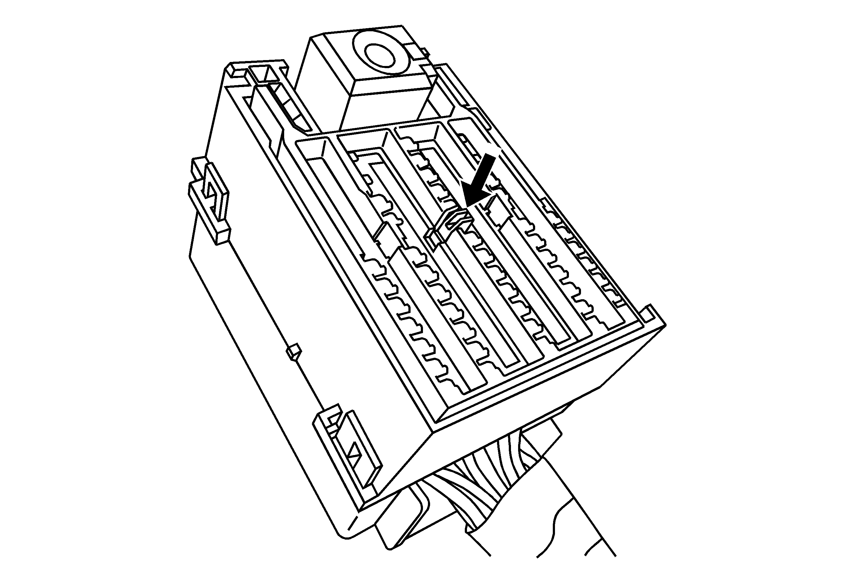
- Unlock and lift up the locking retainer .
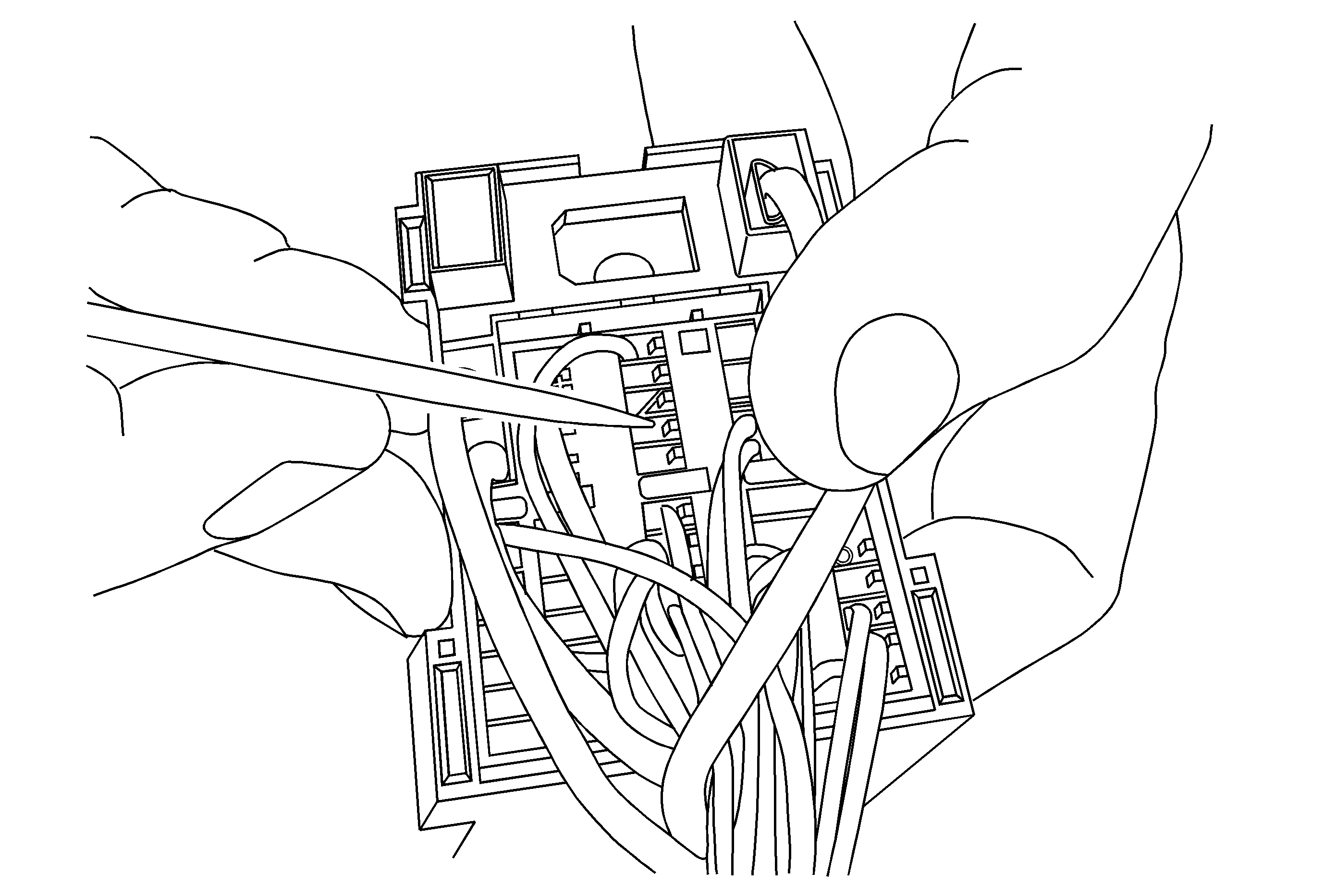
- Install the new harness into cavity 30.
- Install the locking retainer.
- Install the two connectors together.
- Reinstall the electrical center and push down to lock the locking tabs and tighten the two bolts.
- Install a 15 amp fuse in slot F25.
- Reinstall the electrical center cover.
- Reinstall the front compartment side sight shield.
- Connect the negative battery cable.


Tighten
Tighten the three TORX® head bolts to 1.36 N·m(12 lb in).
Tighten
| • | Tighten the M12 bolt to 112 N·m (83 lb ft). |
| • | Tighten the M6 bolt to 9 N·m (80 lb in). |
Tighten
Tighten the bolt to 35 N·m (26 lb ft).
Tighten
Tighten the bolts to 10 N·m (89 lb in).
Parts Information
Part Number | Description | Qty |
|---|---|---|
19116043 | Fuses | 1 |
12337820 | Tie Strap | 2 |
12345382 (US) 10953489 (Canada) | Threadlocker Medium Strength Blue | 1 |
89058946 | Vacuum Pump | 1 |
You must purchase the 12 mm (15/32 in) hose locally.
Warranty Information
For vehicles repaired under warranty, use:
Labor Operation | Description | Labor Time |
|---|---|---|
H9716* | Install Power Brake Booster Pump Kit | 0.7 hr |
* This is a unique labor operation for bulletin use only. It will not be published in the Labor Time Guide. | ||
IMPORTANT NOTE WHEN PRINTING THIS FORM: If the form prints out on two pages, make certain you fax BOTH pages so that the WPC receives all the needed information. Missing information will delay or prevent the part from being shipped.
Parts Request Form - Warranty Parts Center |
|---|
To: Warranty Parts Center
e-mail: [email protected]
or WPC Fax: 248-371-0192
Attn: Jeanette Dunn
Part Being Requested: Vacuum Pump Kit - WPC NUMBER 419
Dealer BAC (U.S.) / Dealer Code (Canada):
Dealer Name:
Dealer Address:
Dealer Contact Person:
Dealer Phone Number:
Repair Order Number:
Vehicle VIN:
Important: If you do not receive the part within 2 business days after e-mailing or faxing your part request to the Warranty Parts Center, please call Customer Assistance at 248-371-9901/9902. IMPORTANT NOTE WHEN PRINTING THIS FORM: If the form prints out on two pages, make certain you fax BOTH pages so that the WPC receives all the needed information. Missing information will delay or prevent the part from being shipped. |
