Coil Installation
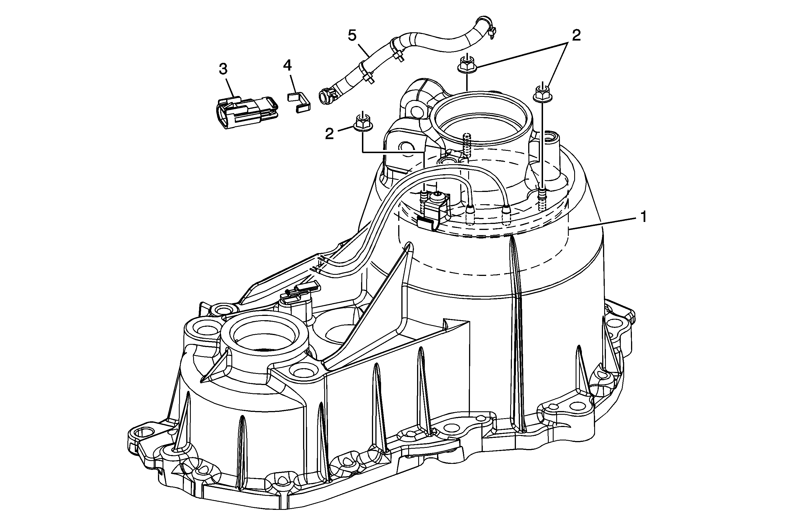
Callout | Component Name |
|---|---|
1 | Transfer Case Coil Assembly |
2 | Transfer Case Coil Nuts (Qty: 3) |
3 | Transfer Case Coil Connector Assembly |
4 | Transfer Case Clip |
5 | Transfer Case Clutch Coil Harness Protector Tip |
Chain Snubber and Vent Baffle Installation
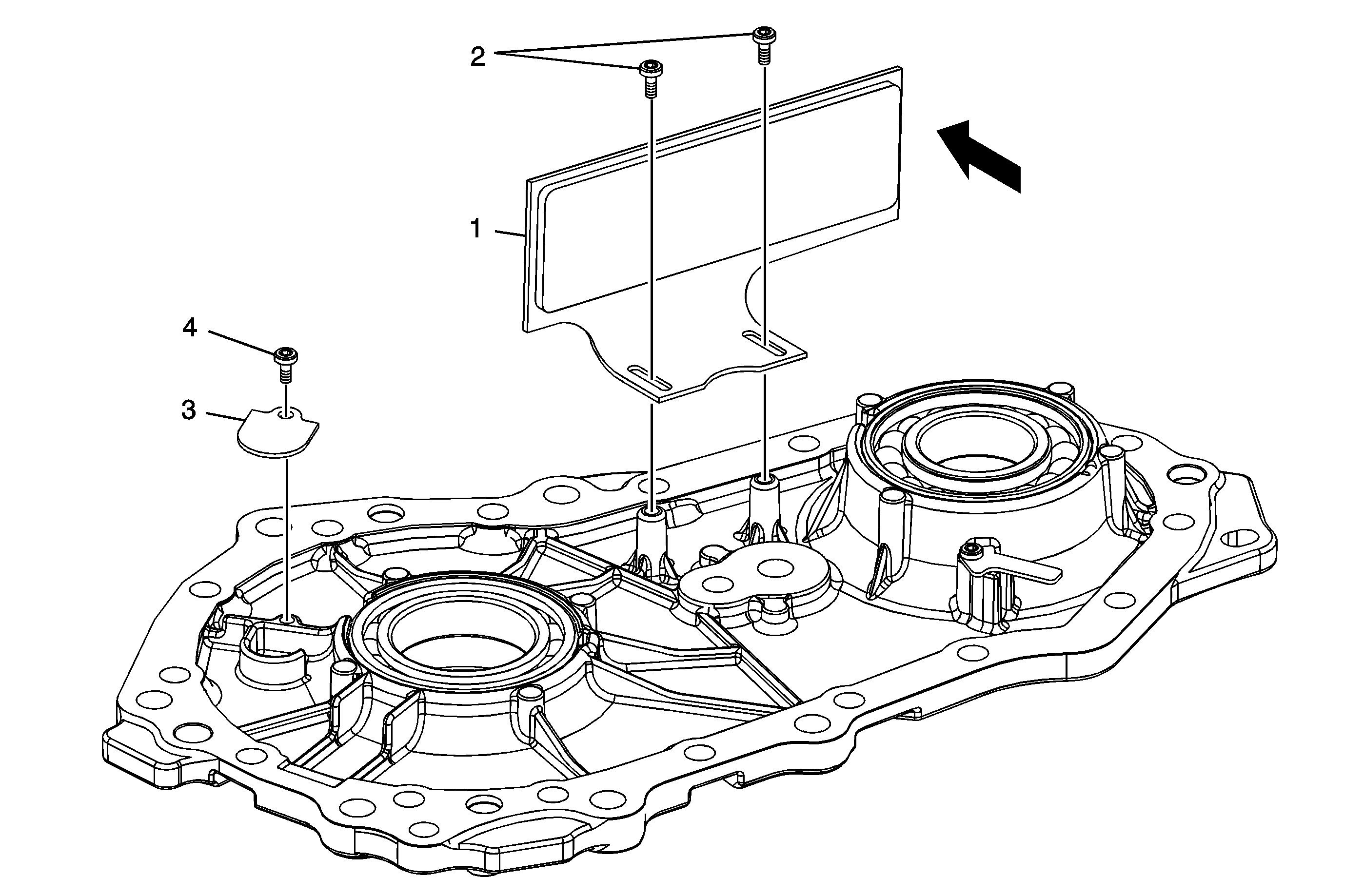
Callout | Component Name | ||||
|---|---|---|---|---|---|
1 | Transfer Case Front Output Shaft Drive Chain Snubber | ||||
2 | Transfer Case Front Output Shaft Drive Chain Snubber Bolts (Qty: 2) Notice: Refer to Fastener Notice in the Preface section. Tip
Tighten | ||||
3 | Transfer Case Vent Baffle | ||||
4 | Transfer Case Vent Baffle Bolt (Qty: 1) Tip
Tighten |
Chain, Sprockets, Oil Pump, Input Shaft, and Front Output Shaft Installation
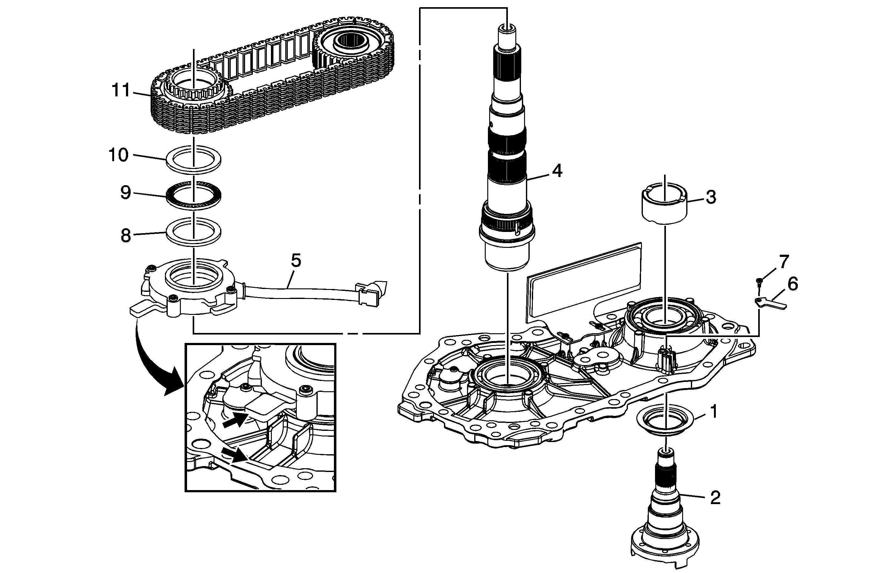
Callout | Component Name | ||||||
|---|---|---|---|---|---|---|---|
1 | Transfer Case Front Output Shaft Seal Dirt Deflector Tip | ||||||
2 | Transfer Case Front Output Shaft | ||||||
3 | Transfer Case Front Output Shaft Driven Sprocket Spacer | ||||||
4 | Transfer Case Input Shaft Assembly | ||||||
5 | Transfer Case Oil Pump Assembly Tip
| ||||||
6 | Transfer Case Oil Pump Suction Hose Clamp | ||||||
7 | Transfer Case Oil Pump Suction Hose Bolt Notice: Refer to Fastener Notice in the Preface section. Tighten | ||||||
8 | Transfer Case Front Output Shaft Drive Sprocket Thrust Washer | ||||||
9 | Transfer Case Front Output Shaft Drive Sprocket Bearing Assembly | ||||||
10 | Transfer Case Front Output Shaft Drive Sprocket Thrust Washer | ||||||
11 | Transfer Case Front Output Shaft Drive Chain Assembly Procedure:Install the drive chain assembly, transfer case front output shaft drive sprocket, and the transfer case front output shaft driven sprocket simultaneously. Tip
|
Apply Cam, and Clutch Pack Installation
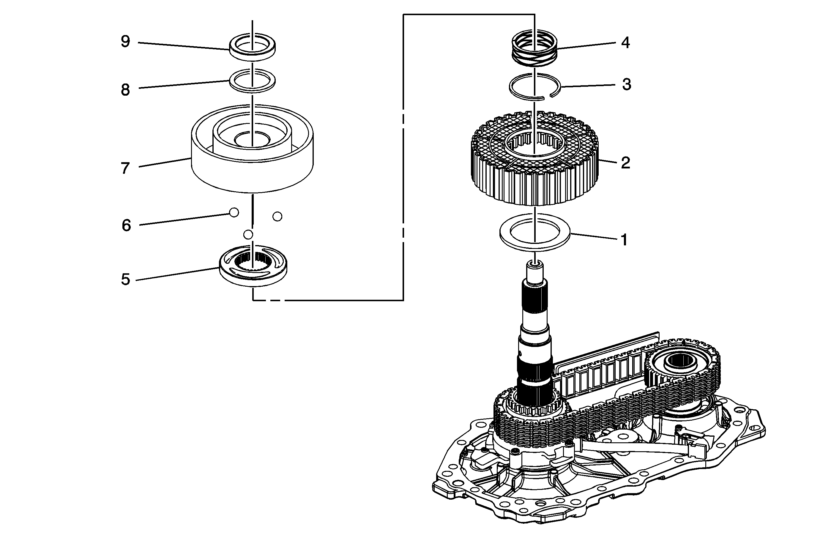
Callout | Component Name | ||||
|---|---|---|---|---|---|
1 | Transfer Case Front Output Shaft Drive Sprocket Spacer | ||||
2 | Transfer Case Clutch Pack Assembly and Armature Tip
| ||||
3 | Transfer Case Snap Ring | ||||
4 | Transfer Case Wave Spring | ||||
5 | Transfer Case Apply Cam | ||||
6 | Transfer Case Balls | ||||
7 | Transfer Case Rotor Assembly | ||||
8 | Transfer Case Thrust Bearing | ||||
9 | Transfer Case Thrust Washer Tip |
Case Half and Front Output Shaft Hole Plug Installation
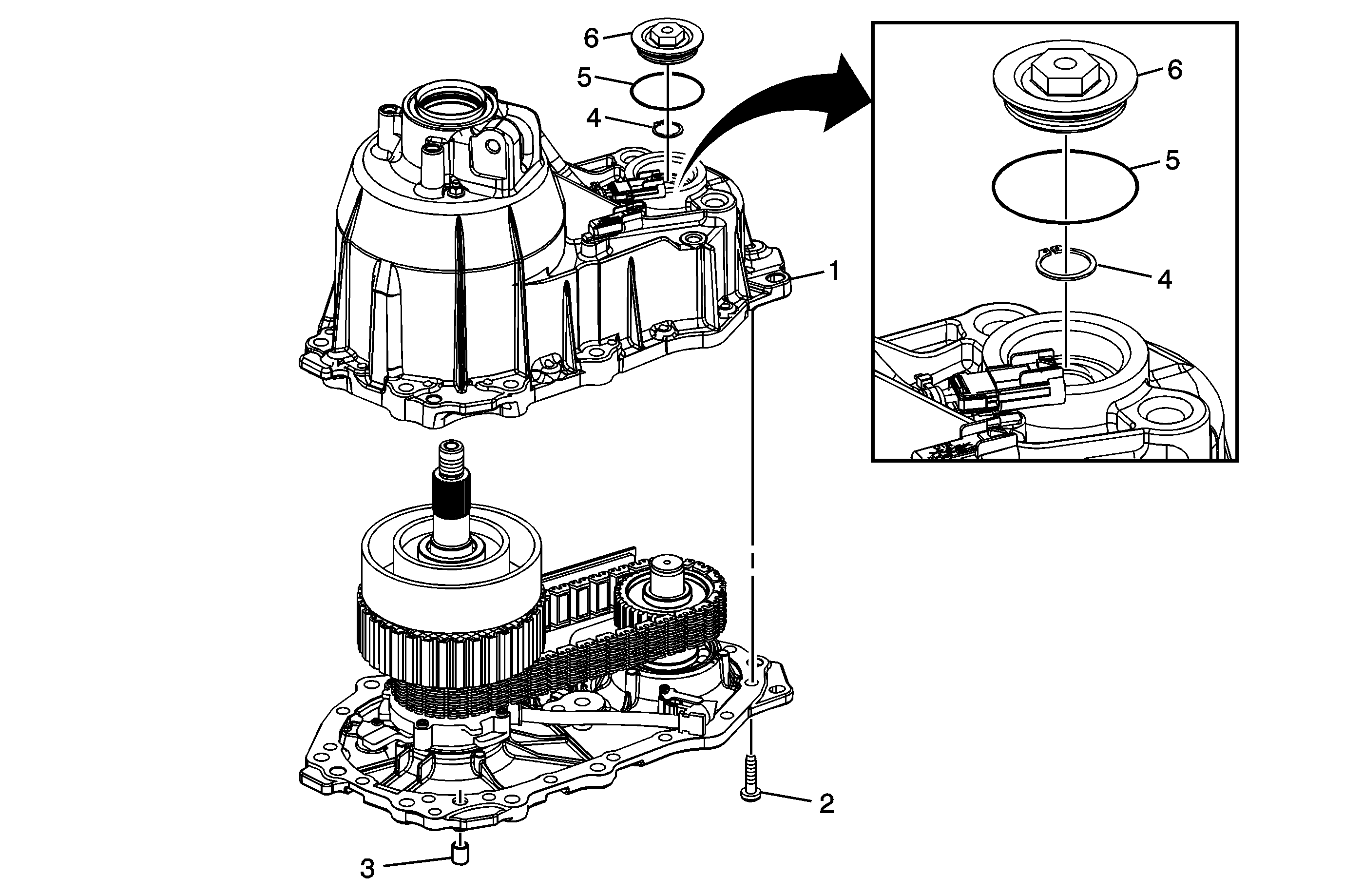
Callout | Component Name |
|---|---|
1 | Transfer Case - Rear Half Tip |
2 | Transfer Case Half Bolt Notice: Refer to Fastener Notice in the Preface section. Tip Tighten |
3 | Transfer Case Location Pin - If Removed |
4 | Transfer Case Front Output Shaft Bearing Retaining Ring |
5 | Transfer Case O-Ring Seal Tip |
6 | Transfer Case Front Output Shaft Hole Plug Tighten |
Dampener and Rear Output Flange Installation
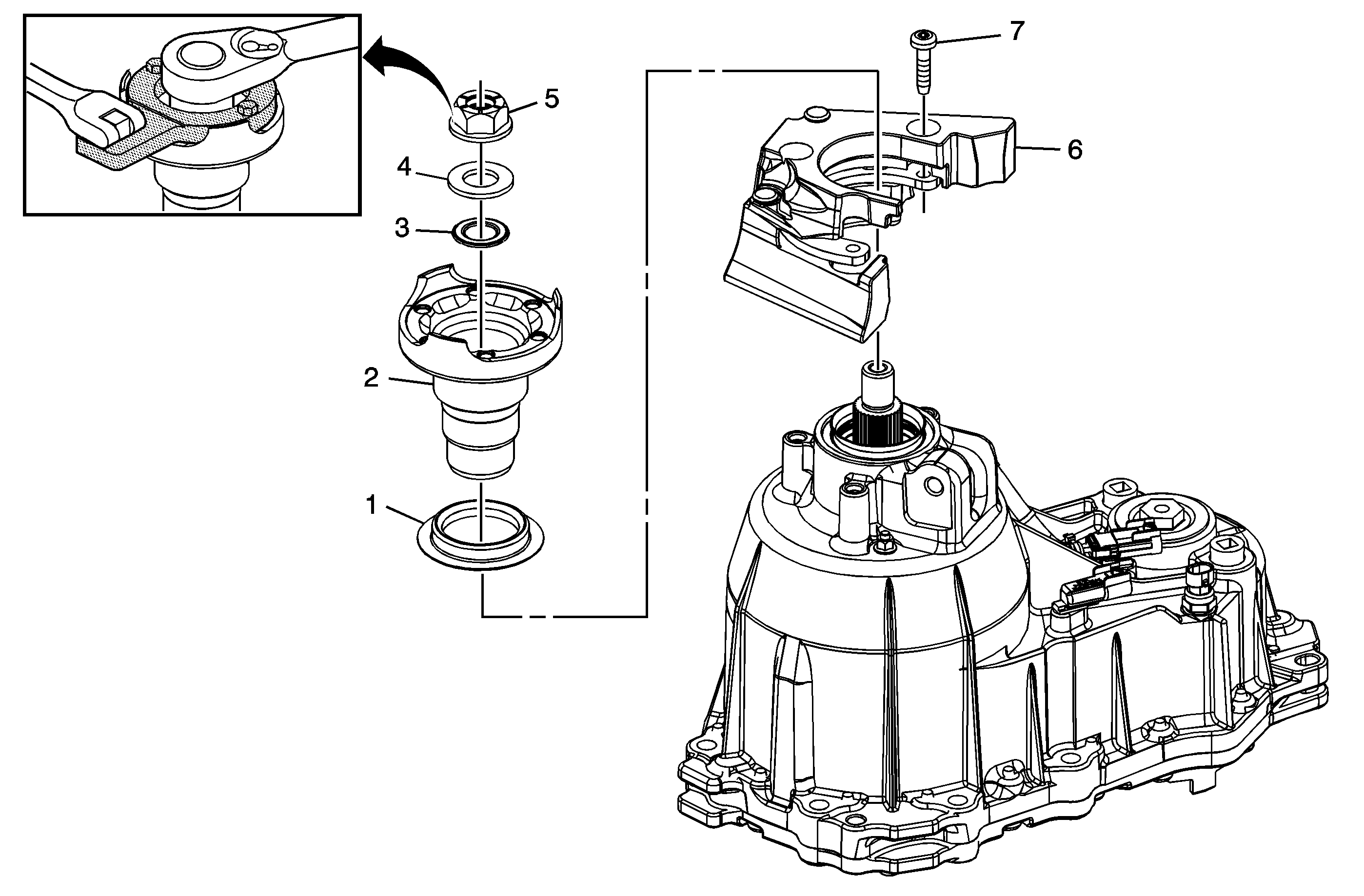
Callout | Component Name |
|---|---|
1 | Transfer Case Rear Output Shaft Seal Dirt Deflector Tip |
2 | Transfer Case Rear Output Shaft Flange Assembly |
3 | Transfer Case Rear Output Shaft Flange O-Ring Seal |
4 | Transfer Case Rear Output Shaft Thrust Washer |
5 | Transfer Case Rear Output Shaft Flange Nut Notice: Refer to Fastener Notice in the Preface section. Tighten Special ToolsDT-48847 Pinion Flange Holder |
6 | Transfer Case Vibration Dampener |
7 | Transfer Case Vibration Dampener Bolt Tighten |
Vent Assembly, Drain Plug, Fill Plug, and Temperature Sensor Installation
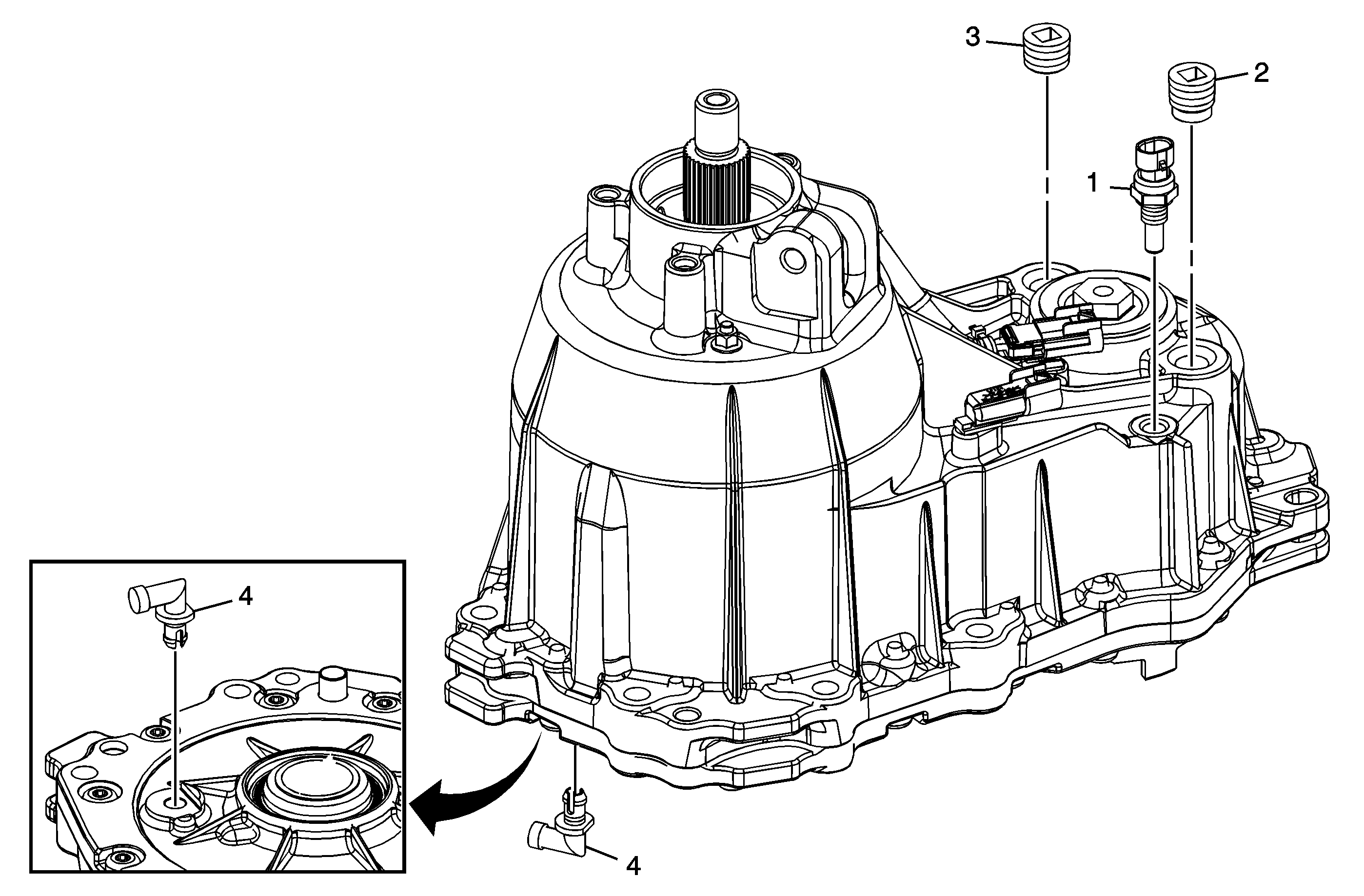
Callout | Component Name | ||||
|---|---|---|---|---|---|
1 | Transfer Case Temperature Sensor Assembly | ||||
2 | Transfer Case Oil Drain Plug - Magnetic Notice: Refer to Component Fastener Tightening Notice in the Preface section. Tip Tighten | ||||
3 | Transfer Case Oil Fill Plug Tip
Tighten | ||||
4 | Transfer Case Vent Assembly |
