For 1990-2009 cars only
Special Tools
| • | J 28467-B Universal Engine Support Fixture |
| • | J-28467-550 Engine Support Beam Adapter |
| • | J 36857 Engine Lift Bracket |
Installation Procedure
- Remove the engine compartment sight shields. Refer to Front Compartment Sight Shields Replacement .
- Remove the cross vehicle brace. Refer to Cross Vehicle Brace Replacement .
- Remove the fuel injector sight shield. Refer to Fuel Injector Sight Shield Replacement .
- Use a grade 10.9, M10 X 1.5 X 35 bolt, GM P/N 11519182 or equivalent, in order to install an engine lift bracket (OTC #7100, J 36857 or equivalent) to the right cylinder head in the location shown.
- Remove the air cleaner outlet duct. Refer to Air Cleaner Outlet Duct Replacement .
- Remove the vacuum pump and position aside, if equipped.
- Remove the power steering reservoir and position aside. Refer to Remote Power Steering Fluid Reservoir Replacement .
- Remove the Bank 2 (Left Side) exhaust camshaft position sensor. Refer to Camshaft Position Sensor Replacement - Bank 2 (Left Side) Exhaust .
- Use a grade 10.9, M10 X 1.5 X 35 bolt, GM P/N 11519182 or equivalent, in order to install an engine lift bracket (OTC #7100, J 36857 or equivalent) to the front of the left cylinder head in the location shown.
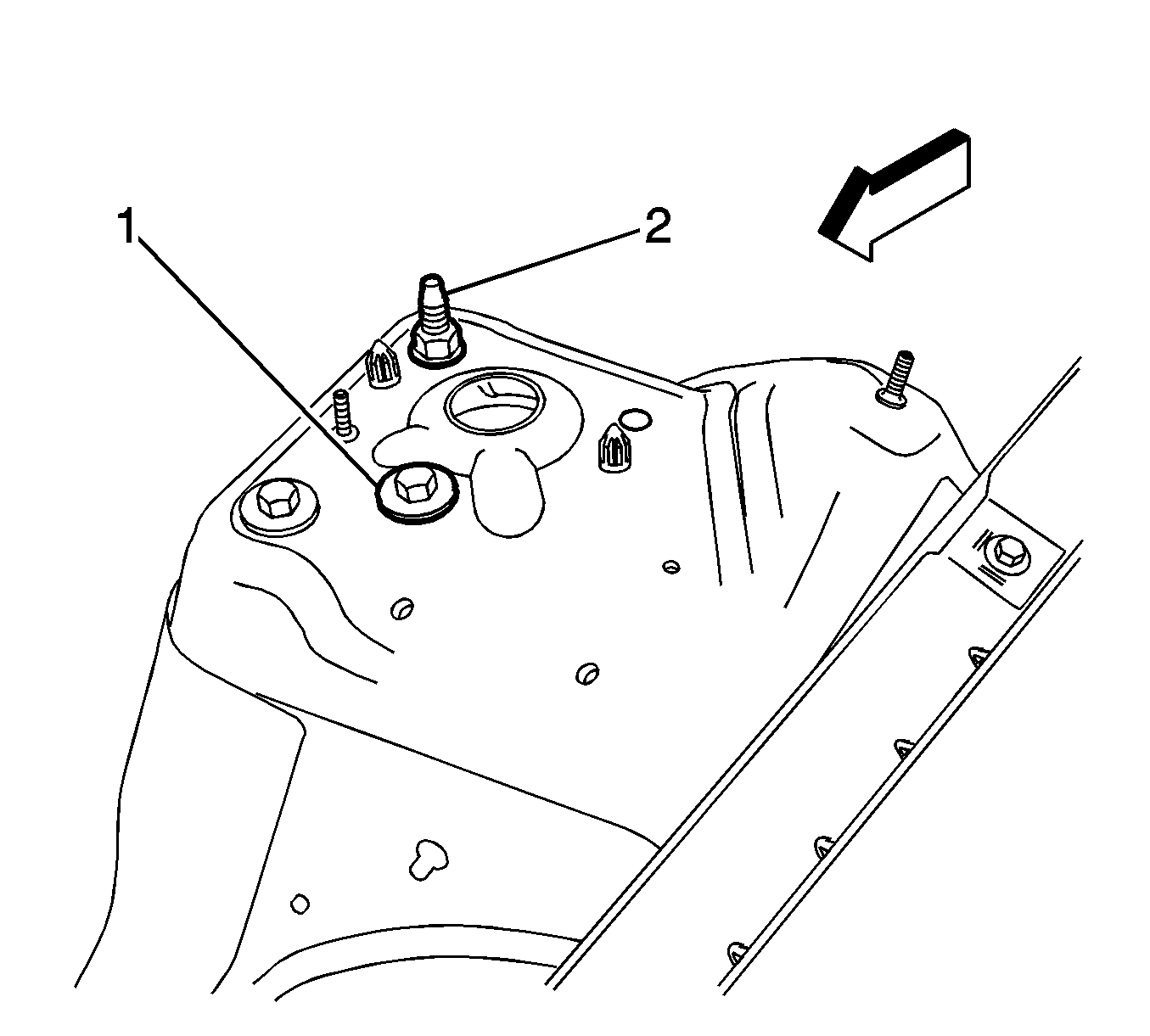
- Remove the shock module mounting stud (2) and bolt (1) from the left and right shock tower.
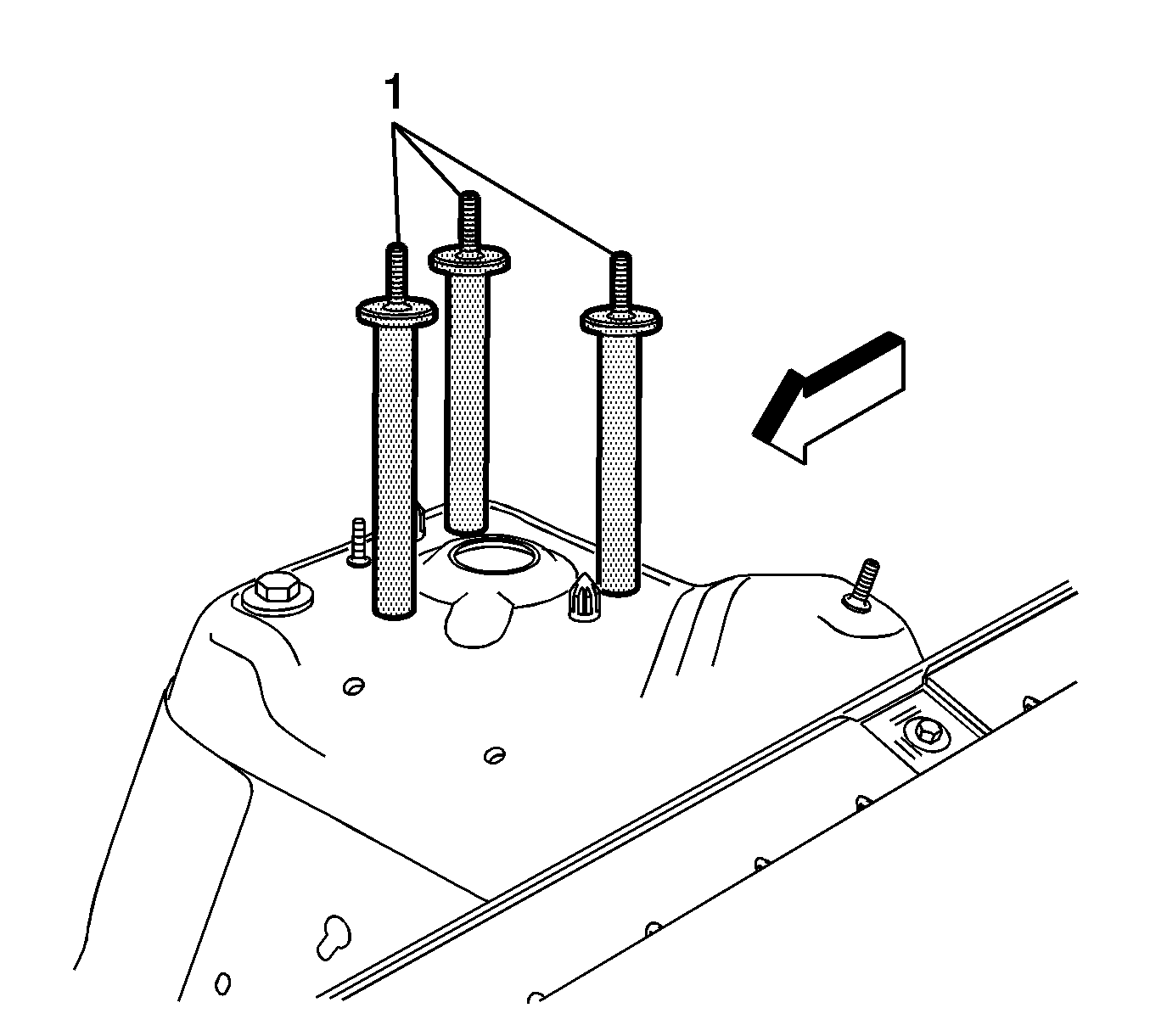
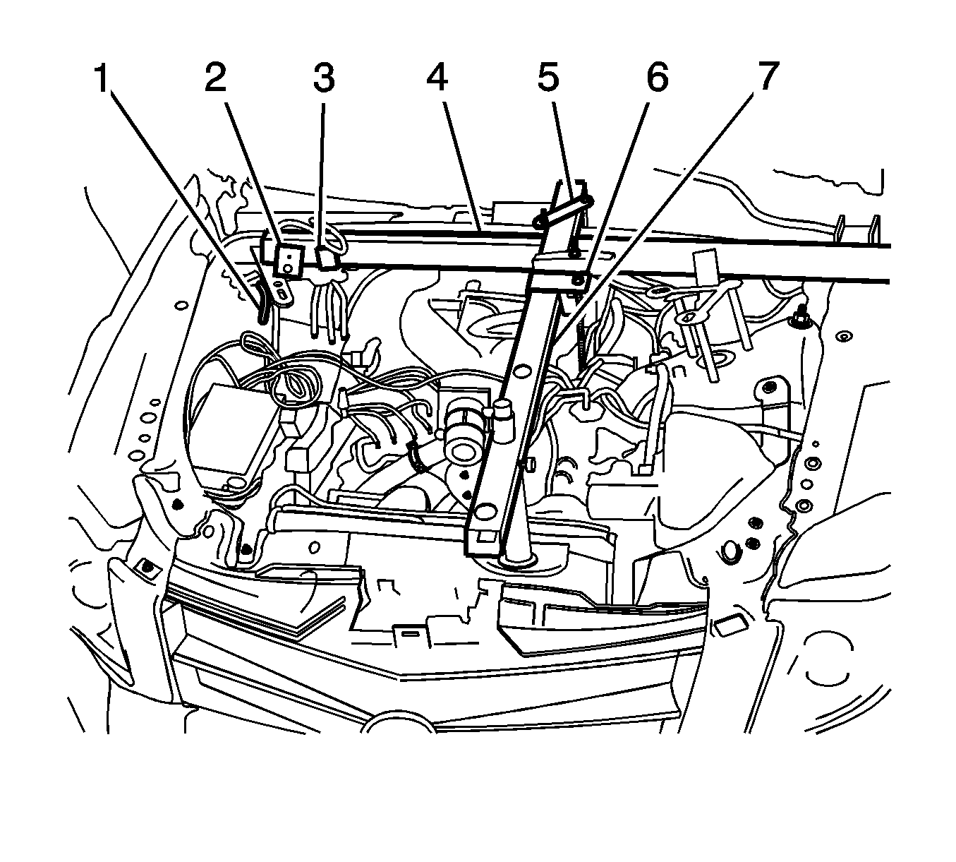
- Install the J-28467-550 (1) in the location shown on the left and right shock towers.
- Ensure the strut tower support assemblies (2) are secured to the engine support beam adapters (1) with wing nuts.
- Secure the strut tower tube (4) to the strut tower support (2) with quick release pins.
- Secure the strut tower tube (4) to the radiator shelf tube (7) with the cross bracket assembly (5).
- Tighten the cross bracket wing nuts.
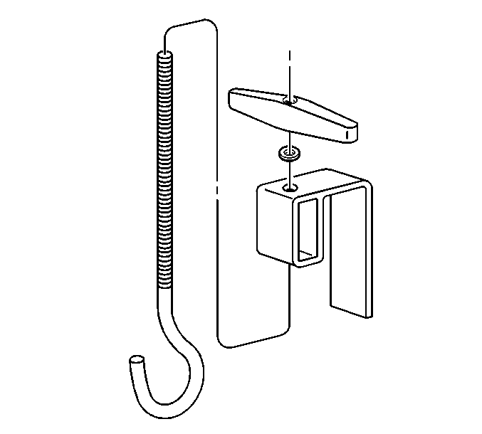
- Assemble the lift hook wing nut and the lift hook bracket to the lift hook.
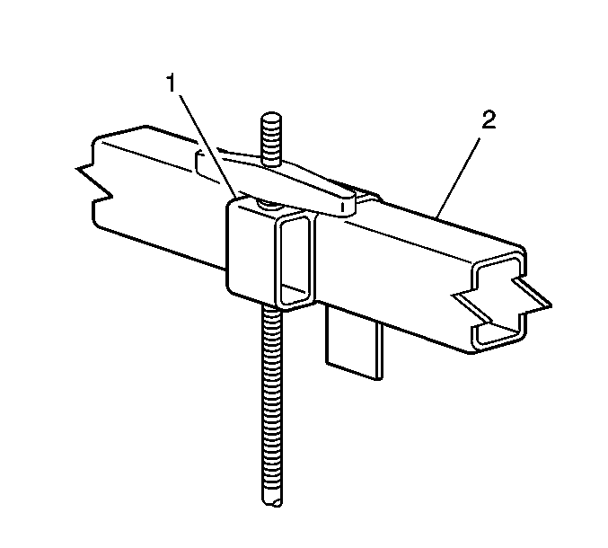
- Install lift hook assembly (1) to the radiator shelf tube (2).
- Install lift hook assembly to left side engine lift hook bracket.
- Assemble the lift hook wing nut and the lift hook bracket to the lift hook.
- Install lift hook assembly (1) to the strut tower tube (2).
- Hand tighten the lift hooks (3, 6) in order to remove all slack from the engine support fixture.
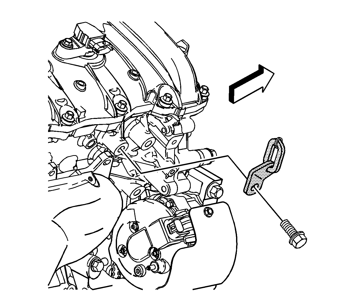
Notice: Refer to Fastener Notice in the Preface section.
Tighten
Tighten the bolt to 65 N·m (48 lb ft).
Important: It is not necessary to remove the hoses from the power steering reservoir.
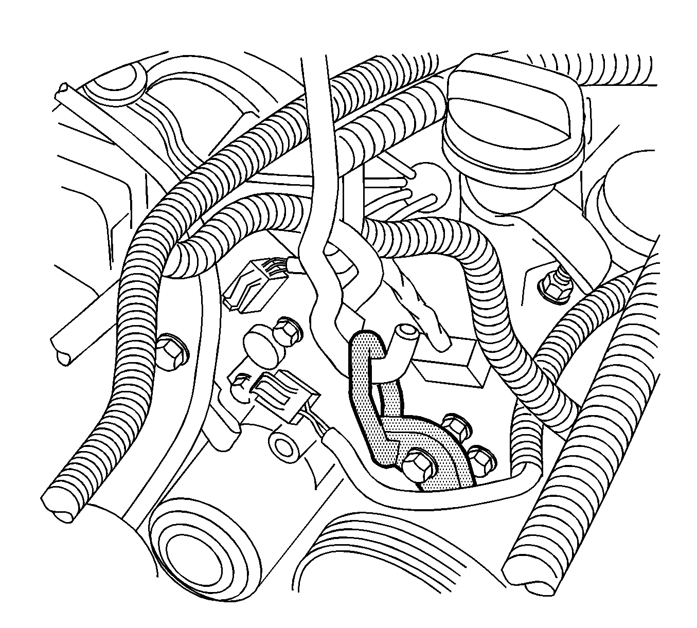
Tighten
Tighten the bolt to 65 N·m (48 lb ft).


Removal Procedure
- Remove the J 28467-B .
- Remove the J-28467-550 .
- Install the shock module mounting stud (2) and bolt (1) to the left and right shock towers.
- Remove the right and left engine lift brackets from the engine.
- Install the Bank 2 (Left Side) exhaust camshaft position sensor. Refer to Camshaft Position Sensor Replacement - Bank 2 (Left Side) Exhaust .
- Install the power steering reservoir. Refer to Remote Power Steering Fluid Reservoir Replacement .
- Install the vacuum pump, if equipped.
- Install the air cleaner outlet duct. Refer to Air Cleaner Outlet Duct Replacement .
- Install the fuel injector sight shield. Refer to Fuel Injector Sight Shield Replacement .
- Install the cross vehicle brace. Refer to Cross Vehicle Brace Replacement .
- Install the engine compartment sight shields. Refer to Front Compartment Sight Shields Replacement .
Notice: Refer to Fastener Notice in the Preface section.

Tighten
Tighten the studs and bolts to 112 N·m (83 lb ft).
