Intake Manifold Cleaning and Inspection LY7/LP1
Upper Intake Manifold Cleaning Procedure
- Remove any remaining gasket and/or gasket material from the following:
- Clean the following intake manifold areas in solvent.
| • | Intake manifold gasket sealing areas |
| • | Intake manifold passages |
| • | Brake booster hose passage |
| • | Evaporative emission (EVAP) solenoid passage |
| • | Positive crankcase ventilation (PCV) vacuum hose passages |
| • | Barometric pressure (BARO) sensor passage |
Caution: Refer to Safety Glasses Caution in the Preface section.
- Dry the upper intake manifold and throttle body with compressed air.
Inspection Procedure
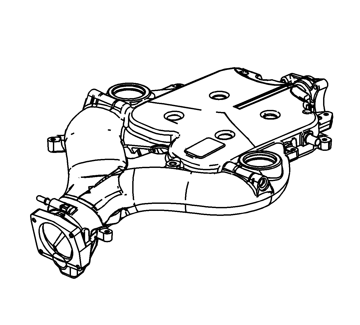
- Inspect the upper intake manifold for the following conditions:
| • | Damage, debris or restrictions to the BARO sensor mounting port |
| • | Damage, debris or restrictions to the brake vacuum booster hose port |
| • | Damage to the throttle body bolt holes |
| • | Damage, debris or restrictions to the PCV system hose ports |
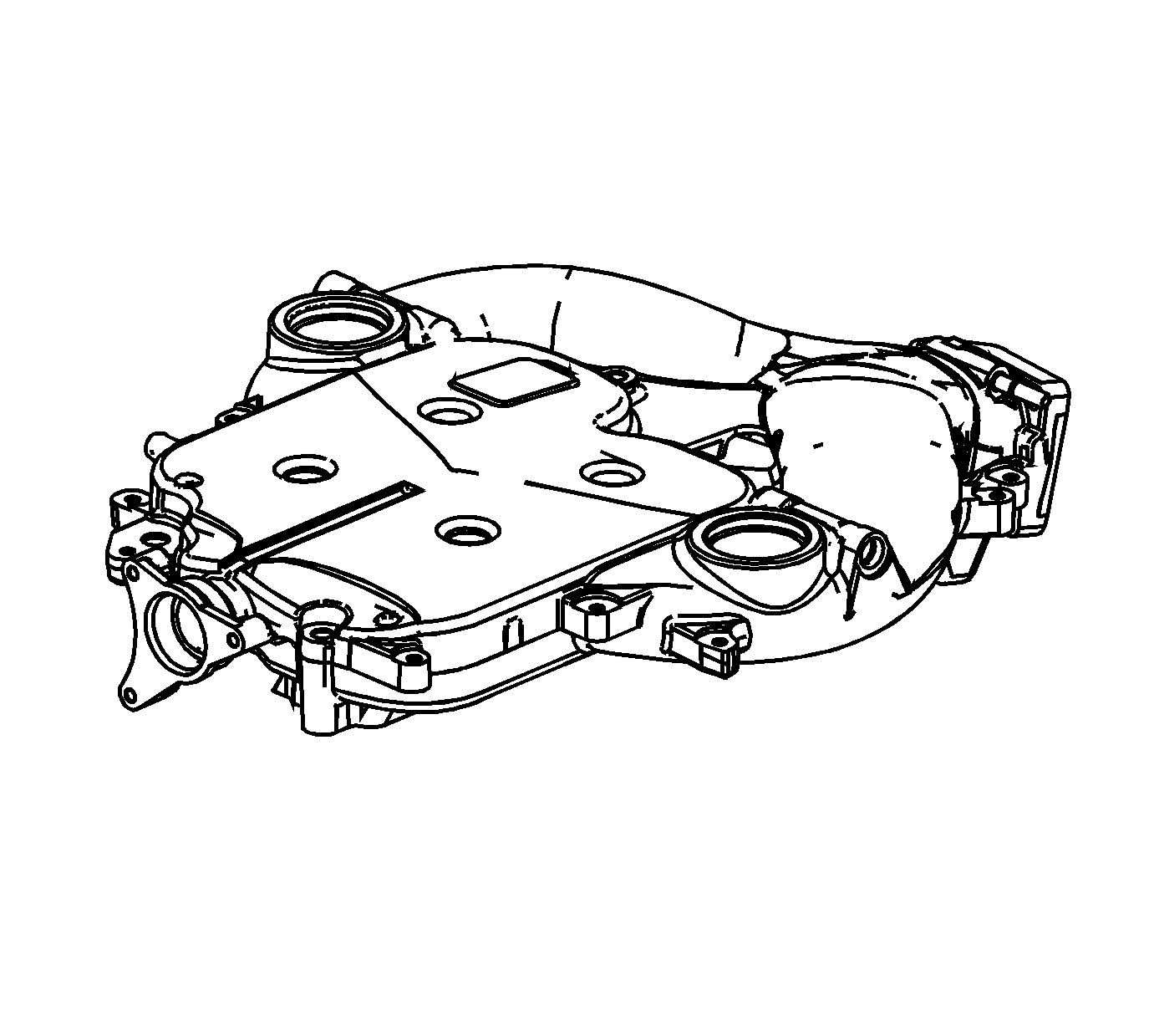
- Inspect the upper intake manifold for the following conditions:
| • | Damage to the intake manifold bolt bosses |
| • | Damage to the EVAP purge solenoid mounting boss |
| • | Damage, debris or restrictions to the EVAP purge solenoid port |
| • | Damage, debris or restrictions in the vacuum passage |
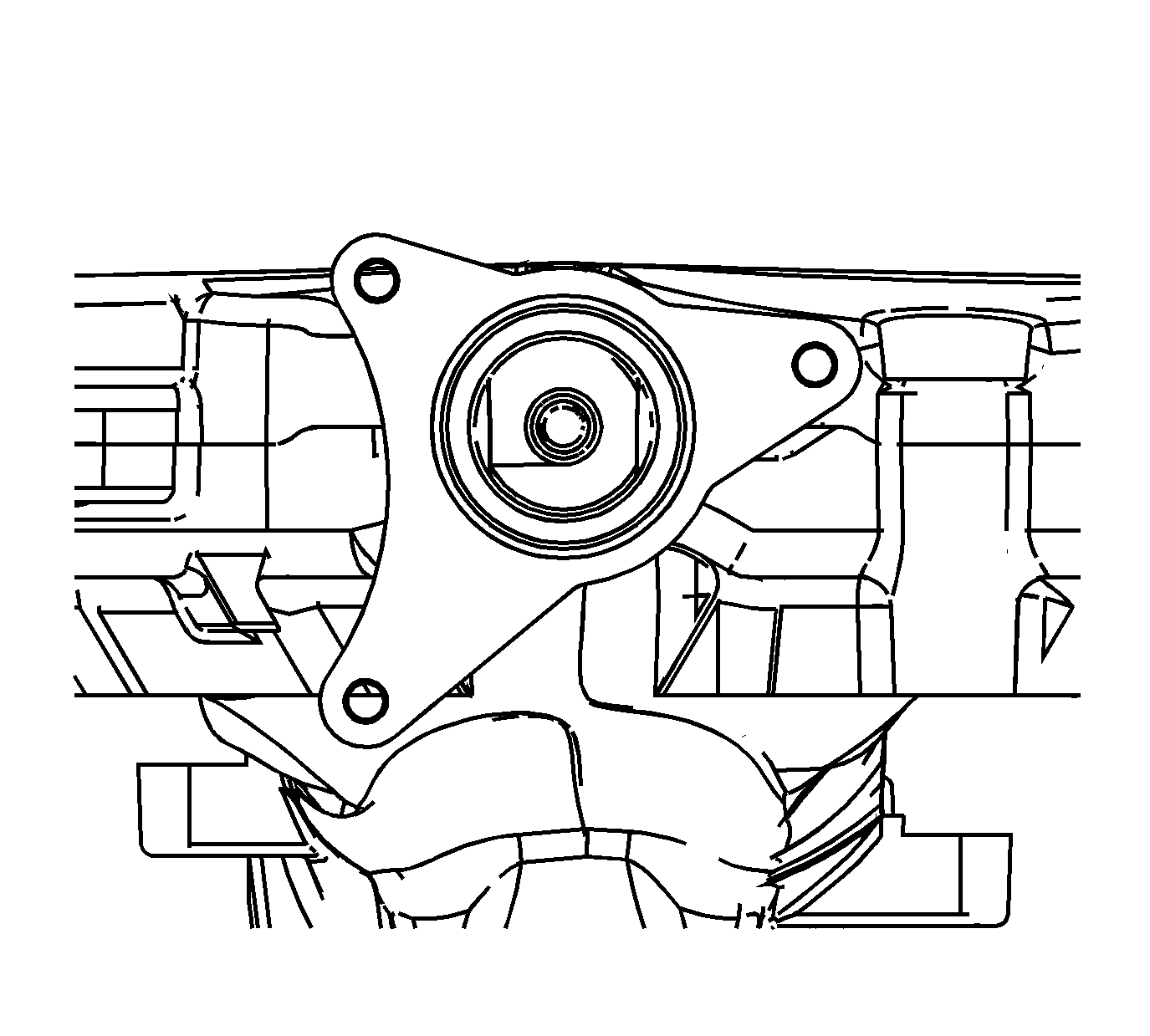
- Inspect the upper intake manifold for the following conditions:
| • | Damage to the communicator valve mounting bosses |
| • | Damage, debris or restrictions to the communicator valve port |
| • | Damage to the communicator valve components |
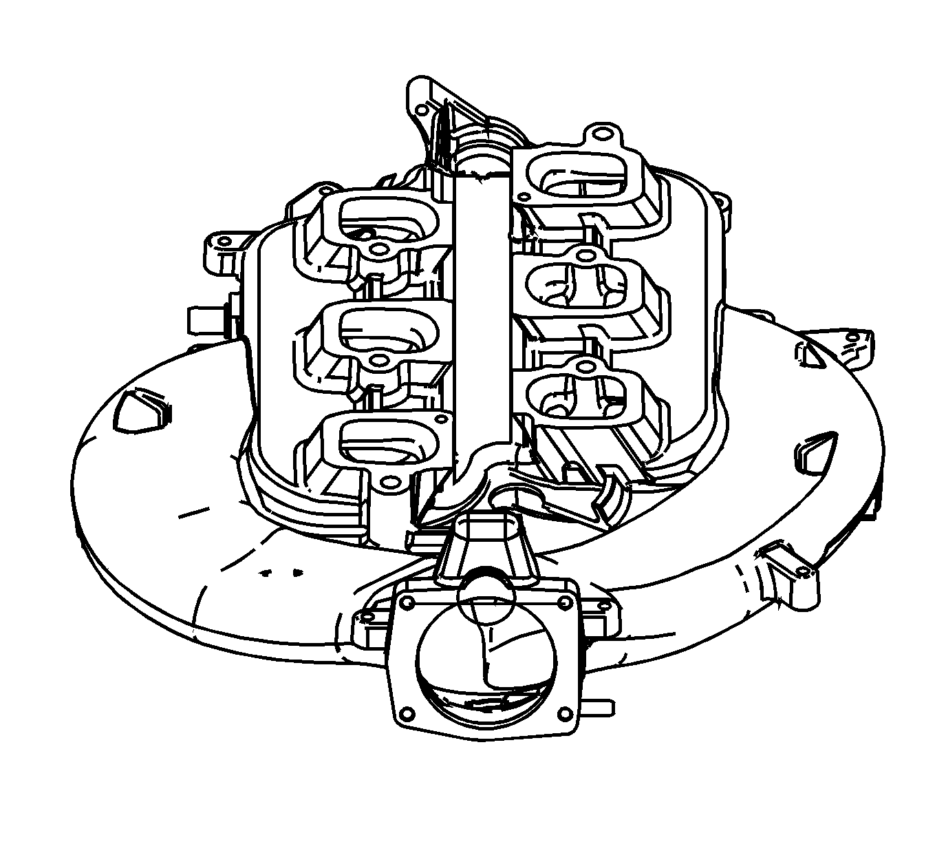
- Inspect the upper intake manifold for the following conditions:
| • | Gouges or damage to the upper intake manifold sealing surfaces |
| • | Damage to the gasket sealing surface for the throttle body |

- Inspect the upper intake manifold sealing surface for warpage.
| 5.1. | Locate a straight edge across the upper-to-lower intake manifold sealing surface. |
| 5.2. | Insert a feeler gage between the upper intake manifold and the straight edge. An upper intake manifold with warpage in excess of 0.50 mm (0.020 in) must be replaced. |
- Repair or replace the upper intake manifold as necessary.
Lower Intake Manifold Cleaning Procedure
- Remove any remaining gasket and/or gasket material from the following:
| • | Upper-to-lower intake manifold sealing surface |
| • | Cylinder head-to-lower intake manifold sealing surface |
- Clean the following intake manifold areas in solvent.
| • | Intake manifold gasket sealing surfaces |
| • | Intake manifold passages |
Caution: Refer to Safety Glasses Caution in the Preface section.
- Dry the intake manifold with compressed air.
Inspection Procedure
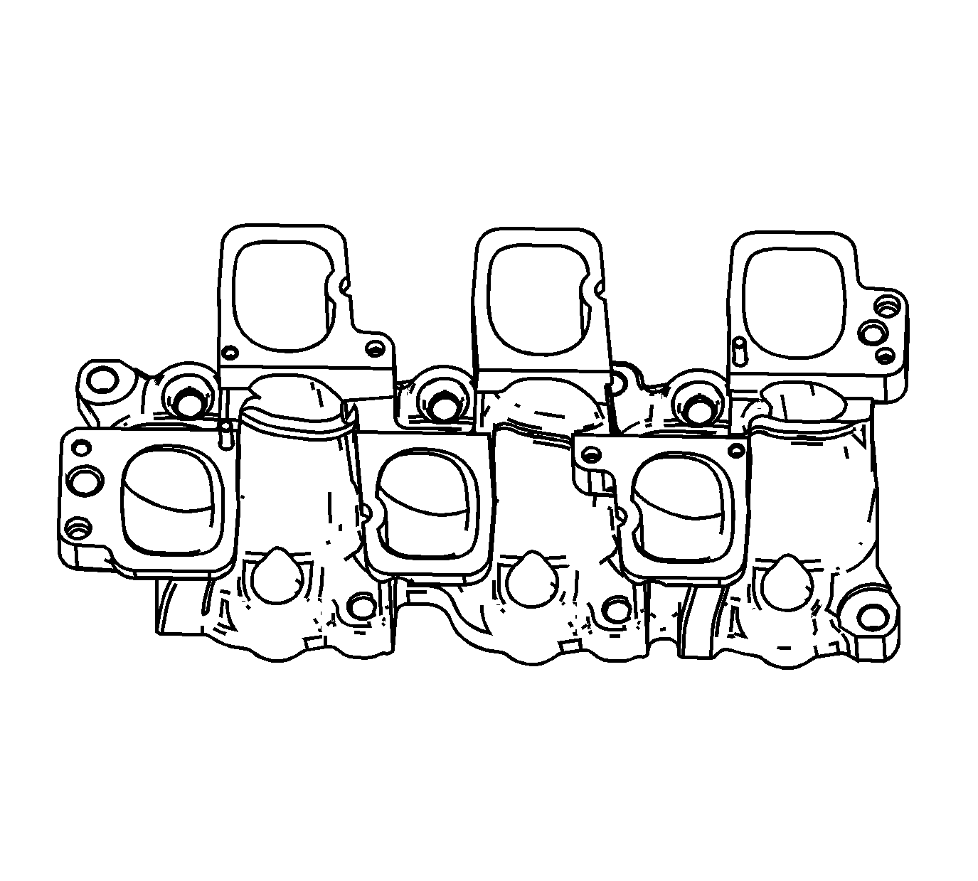
- Inspect the lower intake manifold for the following conditions:
| • | Damage, debris or restrictions to the lower intake manifold ports |
| • | Damage to the fuel rail mounting bolt holes |
| • | Damage to the fuel rail |
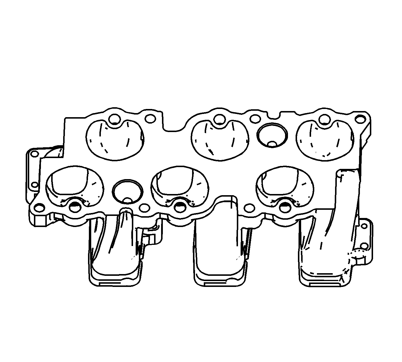
- Inspect the lower intake manifold for the following conditions:
| • | Gouges or damage to the intake manifold sealing surfaces |
| • | Damage to the lower intake manifold bolt bosses |
| • | Damage to the fuel injector ports |
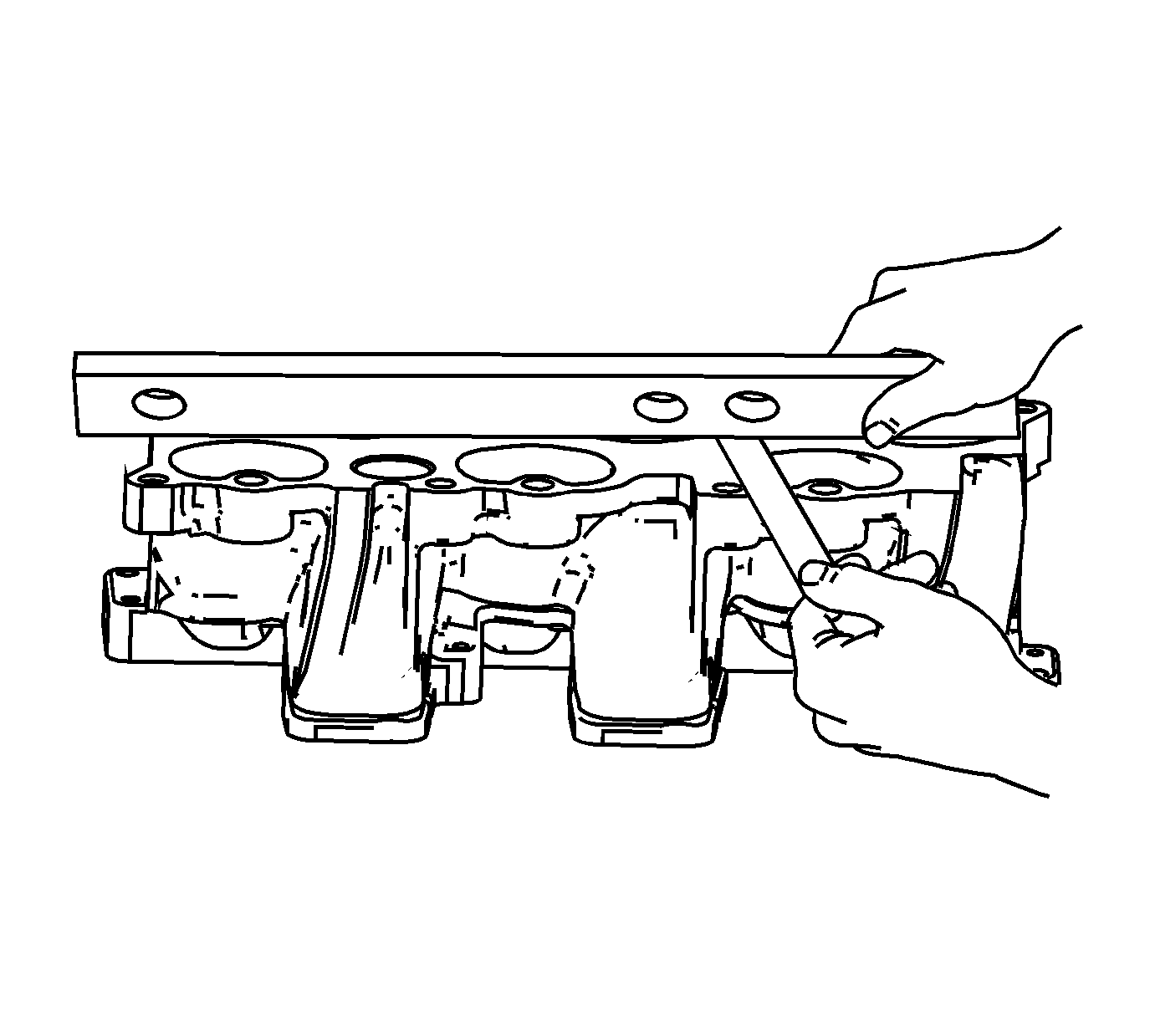
- Inspect the lower intake manifold sealing surfaces for warpage.
| 3.1. | Locate a straight edge across the lower intake manifold sealing surfaces. |
| 3.2. | Insert a feeler gage between the lower intake manifold and the straight edge. A lower intake manifold with warpage in excess of 0.5 mm (0.020 in) must be replaced. |
- Repair or replace the lower intake manifold as necessary.
Intake Manifold Cleaning and Inspection LLT
Upper Intake Manifold Cleaning Procedure
- Remove any remaining gasket and/or gasket material from the following:
- Clean the following intake manifold areas in solvent.
| • | Intake manifold gasket sealing areas |
| • | Intake manifold passages |
| • | Brake booster hose passage |
| • | Evaporative emission (EVAP) solenoid passage |
| • | Positive crankcase ventilation (PCV) vacuum hose passages |
Caution: Refer to Safety Glasses Caution in the Preface section.
- Dry the upper intake manifold and throttle body with compressed air.
Inspection Procedure
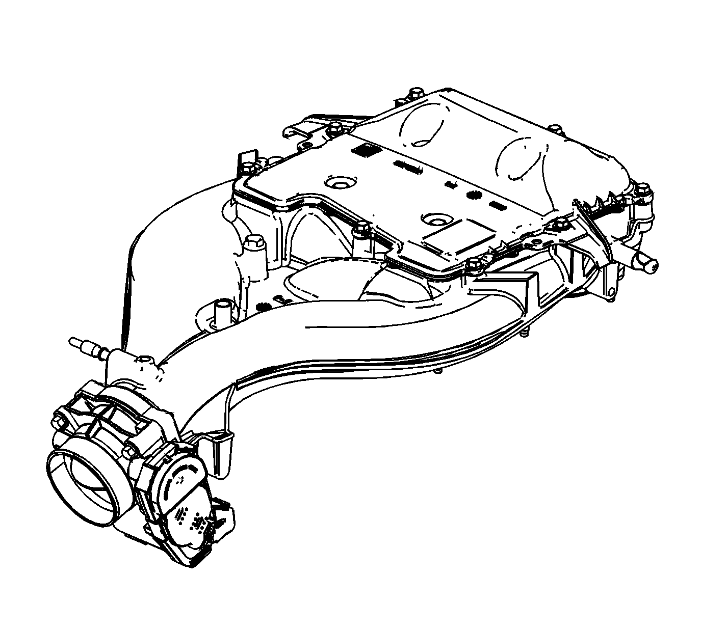
- Inspect the upper intake manifold for the following conditions:
| • | Damage, debris or restrictions to the brake vacuum booster hose port |
| • | Damage to the throttle body bolt holes |
| • | Damage, debris or restrictions to the PCV system hose ports |
| • | Damage to the gasket sealing surface for the intake manifold cover |
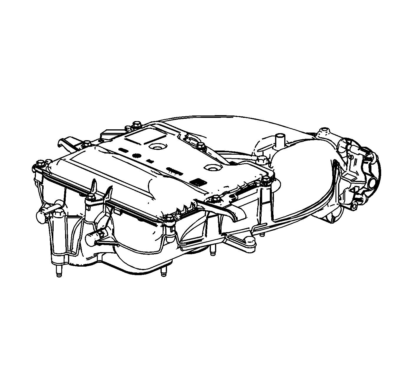
- Inspect the upper intake manifold for the following conditions:
| • | Damage to the intake manifold bolt bosses |
| • | Damage to the EVAP purge solenoid mounting boss |
| • | Damage, debris or restrictions to the EVAP purge solenoid port |
| • | Damage, debris or restrictions in the vacuum passage |

- Inspect the intake manifold for the
following conditions:
| • | Gouges or damage to the intake manifold sealing surfaces |
| • | Damage to the gasket sealing surface for the throttle body |
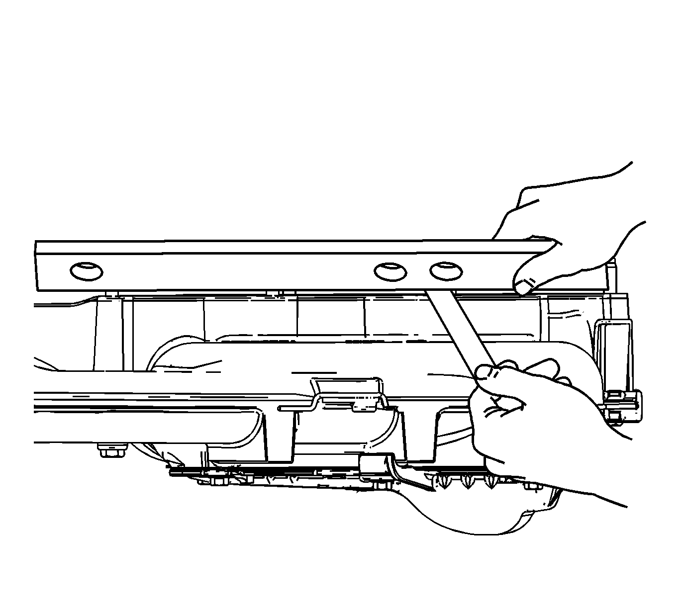
- Inspect the upper intake manifold sealing surface for
warpage.
| 4.1. | Locate a straight edge across the intake manifold sealing surface. |
| 4.2. | Insert a feeler gage between the upper intake manifold and the straight edge. An intake manifold with warpage in excess of 0.50 mm (0.020 in) must be replaced. |
- Repair or replace the upper intake manifold as necessary.


