Stabilizer Shaft Replacement AWD
Removal Procedure
- Raise and support the vehicle. Refer to Lifting and Jacking the Vehicle.
- Remove the tire and wheel. Refer to Tire and Wheel Removal and Installation.
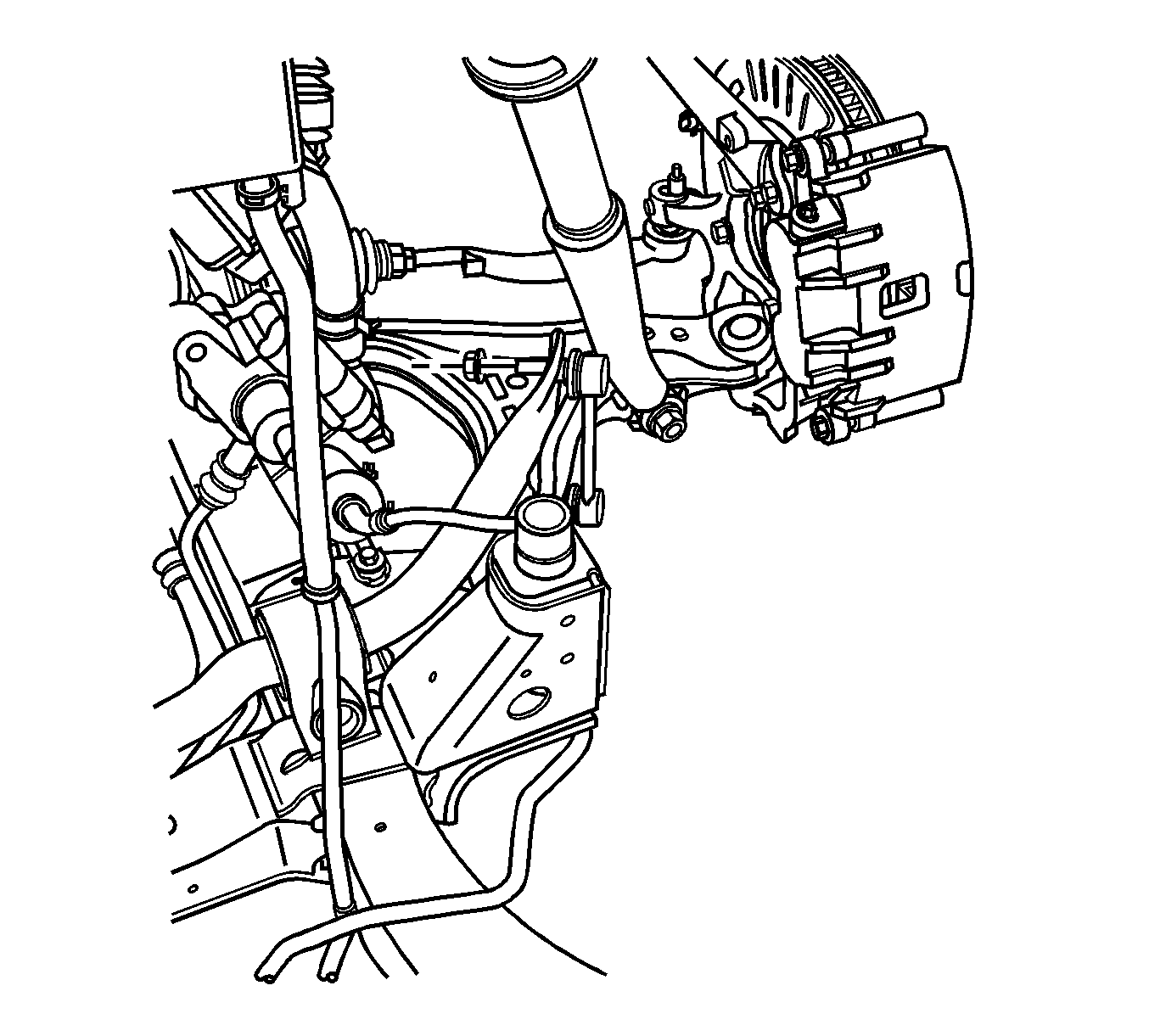
- Remove the stabilizer shaft link to stabilizer shaft retaining nuts. Refer to Stabilizer Shaft Link Replacement.
- Disconnect the stabilizer shaft links from the stabilizer shaft.
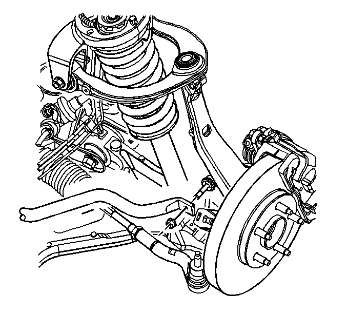
- Remove the stabilizer shaft mounting bolts and brackets.
- Remove the stabilizer shaft insulators from the stabilizer shaft.
- Remove the stabilizer shaft from the vehicle.
Notice: The ball stud must not rotate during disassembly or reassembly. Hand tools must be used to keep the ball stud from rotating. If air tools are used and the stud is allowed to rotate, damage to the ball stud and/or stud mounting hole may occur.

Installation Procedure
- Install the stabilizer shaft to the vehicle.
- Install the stabilizer shaft insulators to the stabilizer shaft. Install the insulator to the stabilizer shaft with the slit facing rearward.
- Install the stabilizer shaft brackets and mounting bolts.
- Connect the stabilizer shaft links to the stabilizer shaft. Refer to Stabilizer Shaft Link Replacement.
- Install the stabilizer shaft link retaining nuts.
- Install the tire and wheel. Refer to Tire and Wheel Removal and Installation.
- Lower the vehicle.
Important: Do not tighten the bolts at this time.

Notice: Refer to Fastener Notice in the Preface section.
Tighten
| • | Tighten the link nuts to 125 N·m (92 lb ft). |
| • | Tighten the bracket bolts to 65 N·m (48 lb ft). |
Stabilizer Shaft Replacement RWD
Removal Procedure
- Raise and support the vehicle. Refer to Lifting and Jacking the Vehicle.
- Remove the tire and wheel. Refer to Tire and Wheel Removal and Installation.
- Disconnect the antilock brake system (ABS) sensor wiring harness from the stabilizer shaft links.
- Remove the stabilizer shaft link to stabilizer shaft retaining nuts.
- Disconnect the stabilizer shaft links from the stabilizer shaft.
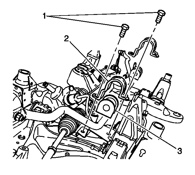
- Remove the stabilizer shaft mounting bolts (1) and brackets (2).
- Remove the stabilizer shaft from the vehicle.
- Remove the stabilizer shaft insulators (3) from the stabilizer shaft.
Notice: The ball stud must not rotate during disassembly or reassembly. Hand tools must be used to keep the ball stud from rotating. If air tools are used and the stud is allowed to rotate, damage to the ball stud and/or stud mounting hole may occur.


Installation Procedure
- Install the stabilizer shaft insulators (3) to the stabilizer shaft. Install the insulator to the stabilizer shaft with the slit facing rearward.
- Install the stabilizer shaft to the vehicle.
- Install the stabilizer shaft brackets (2) and mounting bolts (1).
- Connect the stabilizer shaft links to the stabilizer shaft.
- Install the stabilizer shaft link retaining nuts.
- Connect the ABS sensor wiring harness to the stabilizer links.
- Install the tire and wheel. Refer to Tire and Wheel Removal and Installation.
- Lower the vehicle.

Important: Do not tighten the bolts at this time.

Important: Apply threadlocker 242 or equivalent to the threads of the stabilizer shaft link.
Notice: Refer to Fastener Notice in the Preface section.
Tighten
| • | Tighten the link nuts to 100 N·m (74 lb ft). |
| • | Tighten the bracket bolts to 65 N·m (48 lb ft). |

