For 1990-2009 cars only
Tools required
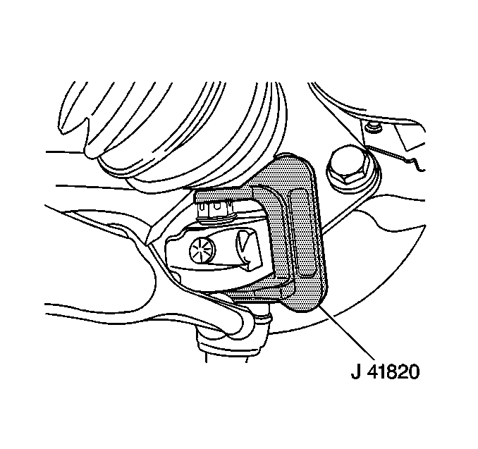
J 41820 Ball Joint/Stud Separator.
Removal Procedure
- Raise and support the vehicle. Refer to Lifting and Jacking the Vehicle .
- Remove the rear wheel. Refer to Tire and Wheel Removal and Installation .
- Remove the wheel bearing/hub. Refer to Rear Wheel Bearing and Hub Replacement .
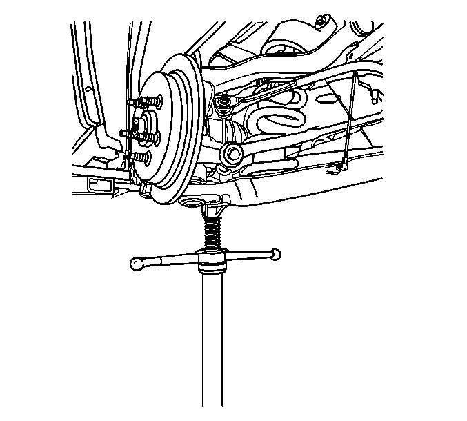
- Use a utility stand in order to support the lower control arm.
- Disconnect the tie rod from the knuckle.
- If necessary, disconnect the height sensor link from the lower control arm.
- Disconnect the upper control arm from the knuckle.
- Loosen the lower ball joint nut, but DO NOT remove.
- Use the J 41820 in order to disengage the ball joint from the knuckle.
- Remove the J 41820 .
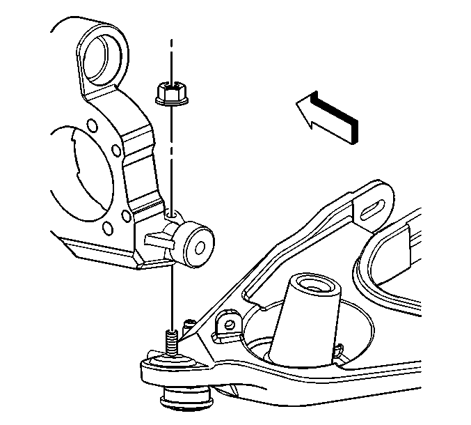
- Remove the ball joint to knuckle nut.
- Remove the knuckle from the vehicle.
- Remove the wheel speed sensor connector bracket.


Installation Procedure
- Install the wheel speed sensor connector bracket to the knuckle.
- Install the wheel speed sensor connector bracket bolt and nut.
- Install the knuckle into the vehicle.
- Install the ball joint to the knuckle nut.
- Connect the upper control arm to the knuckle.
- If necessary, connect the height sensor link to the lower control arm.
- Connect the tie rod to the knuckle.
- Remove the utility stand supporting the lower control arm.
- Install the wheel bearing/hub. Refer to Rear Wheel Bearing and Hub Replacement .
- Install the rear wheel. Refer to Tire and Wheel Removal and Installation .
- Lower the vehicle.
Notice: Refer to Fastener Notice in the Preface section.
Tighten
Tighten the wheel speed sensor bracket nut to 12 N·m
(106 lb in).

Tighten
Tighten the ball joint nut to 35 N·m
(26 lb ft) plus 130 degrees.

Tighten
Tighten the upper control arm nut to 85 N·m
(63 lb ft).
Tighten
Tighten the tie rod nut to 80 N·m (59 lb ft).

