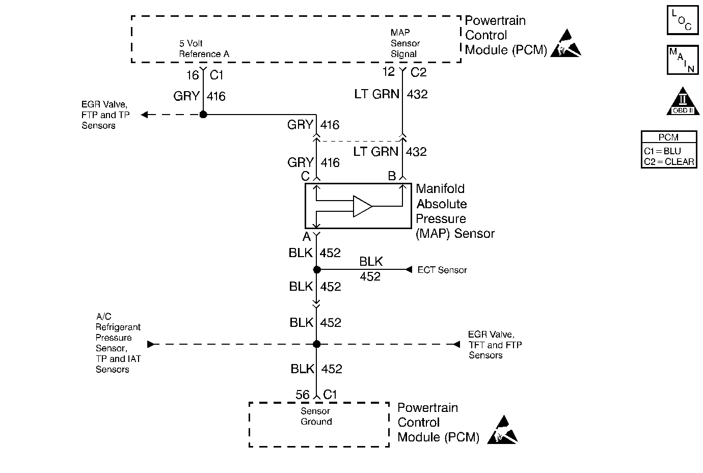
Step
| Action
| Value(s)
| Yes
| No
|
1
| Was the
Powertrain On Board Diagnostic (OBD) System Check
performed?
| --
|
Go to Step 2
| Go to
Powertrain On Board Diagnostic (OBD) System Check
|
2
|
- Check for the following conditions:
| • | MAP sensor seal missing or damaged. |
| • | Vacuum hoses disconnected, damaged, incorrectly routed. |
| • | Intake manifold vacuum leaks. |
| • | Vacuum leaks at throttle body. |
| • | Vacuum leaks at EGR valve flange and pipes. |
| • | Positive crankcase ventilation valve faulty, missing, or incorrectly
installed. |
- If a problem is found, repair as necessary.
Was a problem found?
| --
|
Go to Step 14
| Go to Diagnostic Aids
|
3
|
- Disconnect the MAP sensor electrical connector.
- Observe the MAP value displayed on the scan tool.
Is the MAP value displayed near the specified value?
| 0.0 V
|
Go to Step 4
|
Go to Step 12
|
4
|
- Connect a test light between battery positive voltage and the
MAP sensor signal circuit at the MAP sensor harness connector.
- Observe the MAP value displayed on the scan tool.
Is the MAP value displayed near the specified value?
| 4.95 V
|
Go to Step 5
|
Go to Step 8
|
5
|
- Jumper the 5 Volt Reference A circuit and the MAP signal
circuit together at the MAP sensor harness connector.
- Observe the MAP value displayed on the scan tool.
Is the MAP value displayed near the specified value?
| 4.95 V
|
Go to Step 6
|
Go to Step 7
|
6
|
- Turn the ignition off.
- Disconnect the PCM and check the sensor ground circuit for high
resistance, an open between the PCM and the MAP sensor or for a poor connection
at the PCM.
- If a problem is found, repair as necessary. Refer to Repair Procedures in Electrical Diagnosis.
Was a problem found?
| --
|
Go to Step 14
|
Go to Step 10
|
7
|
- Check the 5 Volt Reference A circuit for high resistance,
an open between the PCM and the MAP sensor or a poor connection at the PCM.
- If a problem is found, repair as necessary. Refer to Repair Procedures in Electrical Diagnosis.
Was a problem found?
| --
|
Go to Step 14
|
Go to Step 9
|
8
|
- Turn the ignition off.
- Disconnect the PCM, and check the MAP sensor signal circuit for
high resistance, an open, a short to ground, or a short to the sensor ground
circuit.
- If a problem is found, repair as necessary. Refer to Repair Procedures in Electrical Diagnosis.
Was a problem found?
| --
|
Go to Step 14
|
Go to Step 9
|
9
|
- Check the MAP sensor signal circuit for a poor connection at the
PCM.
- If a problem is found, repair as necessary. Refer to Repair Procedures in Electrical Diagnosis.
Did the terminal(s) require replacement?
| --
|
Go to Step 14
|
Go to Step 13
|
10
|
- Check for a poor connection at the MAP sensor.
- If a problem is found, repair as necessary. Refer to Repair Procedures in Electrical Diagnosis.
Was a problem found?
| --
|
Go to Step 14
|
Go to Step 11
|
11
| Replace the MAP sensor. Refer to
Manifold Absolute Pressure Sensor Replacement
.
Is the action complete?
| --
|
Go to Step 14
| --
|
12
|
- Turn the ignition off, disconnect the PCM.
- Ignition on, check the MAP signal circuit for a short to voltage
or a short to the 5 volt reference A circuit.
- If a problem is found, repair as necessary. Refer to Repair Procedures in Electrical Diagnosis.
Was a problem found?
| --
|
Go to Step 14
|
Go to Step 13
|
13
| Replace the PCM.
Important: : The replacement PCM must be programmed. Refer to
Powertrain Control Module Replacement/Programming
.
Is the action complete?
| --
|
Go to Step 14
| --
|
14
| With engine idling, monitor MAP Sensor with
scan tool while increasing engine RPM.
Does MAP sensor value change?
| --
| System OK
|
Go to Step 2
|

