1987 REGAL GNX SERVICE MANUAL WARRANTY SUPPLEMENT/PARTS LIST

1987 REGAL GNX SERVICE MANUAL, LIMITED WARRANTY SUPPLEMENT AND PARTS LIST
MODELS AFFECTED: 1987 REGAL GNX
Attached for the 1987 Regal GNX is the following:
o Update supplement for the 1987 Chassis Service Manual to include the 1987 Regal GNX.
o New Car Limited Warranty Supplement (Included with this bulletin).
o Buick Regal GNX Service Parts List.
1987 Buick Regal GNX Service Parts List
Attached is the service parts list for the 1987 Buick Regal GNX (G0434 W/GNX-T2L). The applicable service parts for this vehicle are listed in catalog group order in the same fashion as our regular service catalogs. This listing should be used to identify and order the appropriate, exclusive service parts for this limited build vehicle. Service parts which are common with a regular Buick Regal are not shown within this listing. Please refer to your 1982-87 Buick 44W Catalog for these service parts.
NOTICE: GMSPO will screen all dealer orders for exclusive GNX Service Parts shown on this bulletin. The dealer will be required to provide the VIN, engine serial number, and turbocharger serial number of the GNX vehicle being serviced. All three numbers must match a listing maintained at GM Service Parts Operations before a service art order will be processed. Parts identified by an asterisk (*) in this listing will not have their orders "screened" as described above because they are service parts common to other GM vehicles.
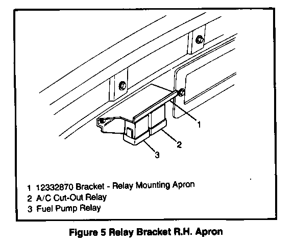
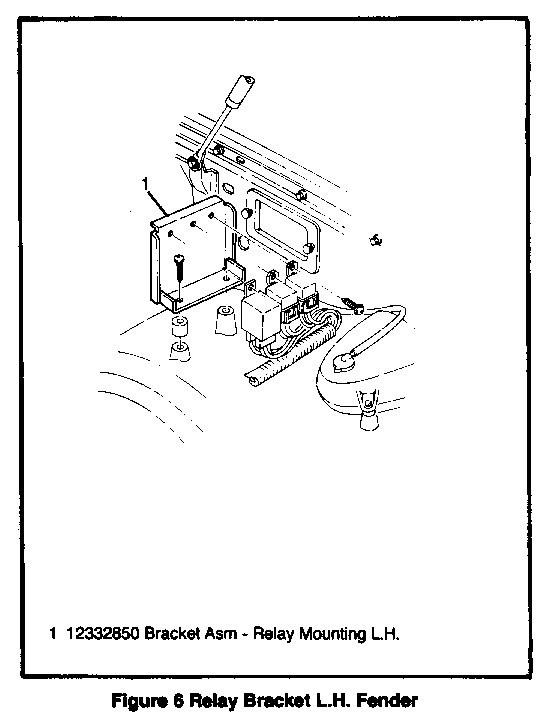
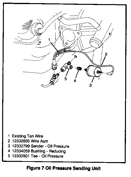
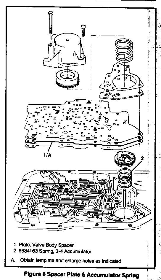
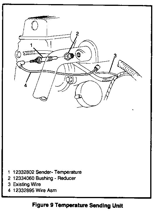
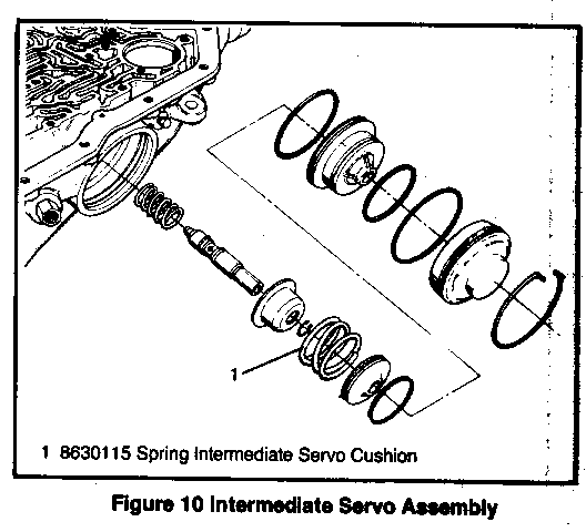
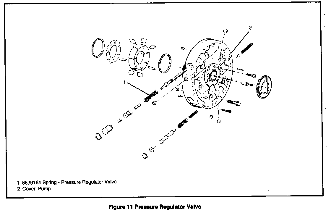
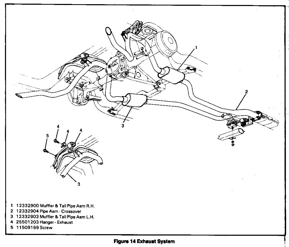
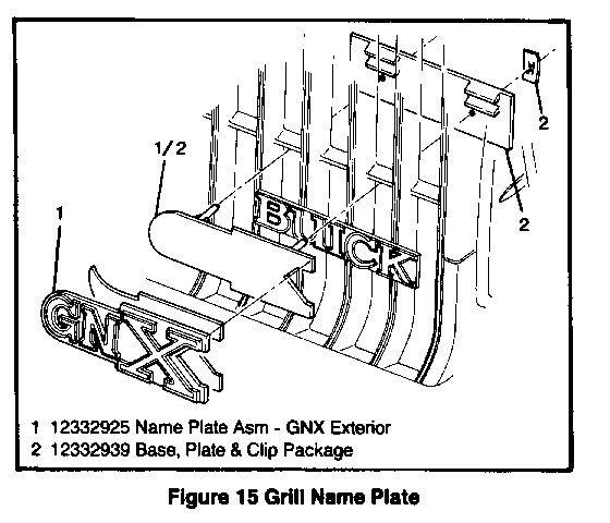
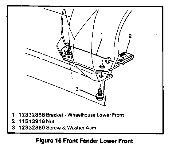
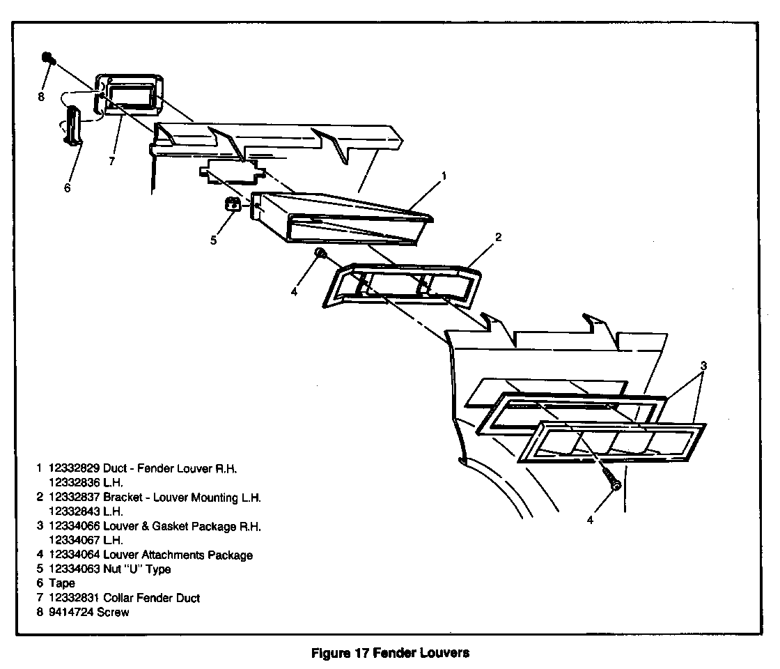
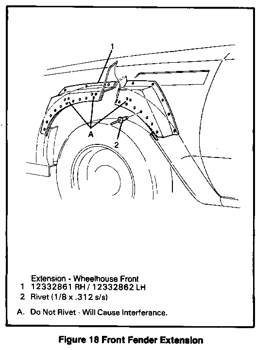
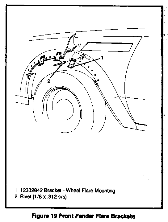
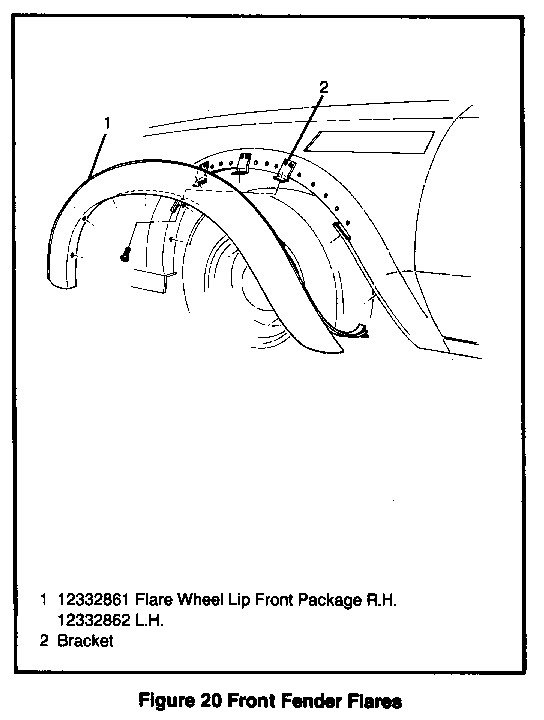
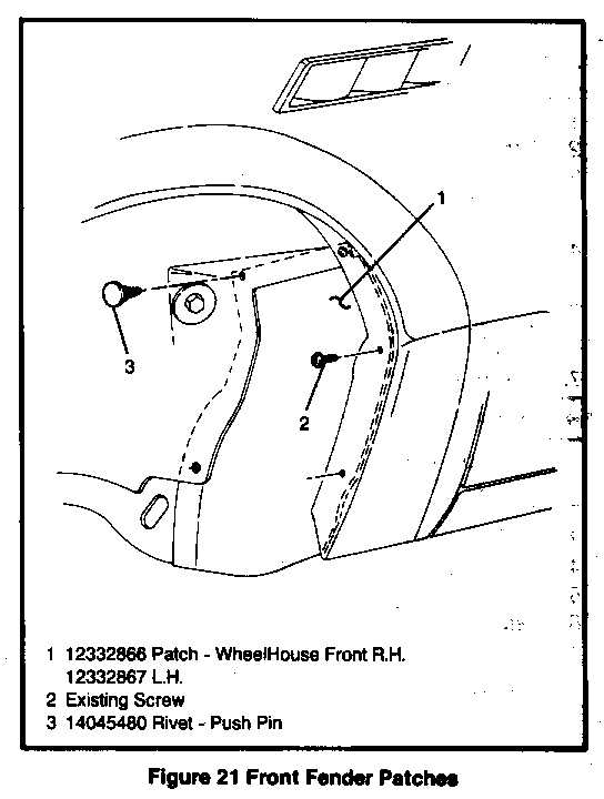
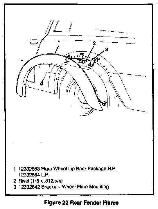
GROUP PART NUMBER QTY DESCRIPTION ----- ----------- --- ----------- 1.148 12332803 1 Gage, Temperature 1.150 12332802 1 Sender, Temperature 1.303 22527473 2 Clip, Grille Nameplate 1.303 12332925 1 Nameplate Assy., Grille 1.303 12332939 1 Nameplate Attachment Pkg, Grille 1.800 12332799 1 Sender, Oil Pressure 1.800 12332895 1 Wire Assy., Oil Pressure Sender 1.803 12332800 1 Gage, Oil Pressure 1.803 12332801 1 Tee, Oil Pressure 2.510 11505166 1 Bolt, Rly Mtg Bracket, LH 2.510 12332850 1 Bracket Assy, RLY Mtg, LH 2.510 12332870 1 Bracket, RLY Mounting Apron 2.510 12332871 1 Bracket, RLY Mtg Blow Hsg 2.510 *20547501 1 Screw, Rly Mtg, Blow Hsg Bracket 3.108 12332808 1 Gage, Fuel 3.336 *25516408 1 Gasket, Turbo Adapter 3.342 12332905 1 Brkt Assy, Turbo Mounting 3.342 12332911 1 Cover, Turbocharger 3.342 *11501033 1 Nut, Turbo (8.917) 3.342 12332909 1 Turbocharger Assembly 3.358 * 1256780 1 Gasket, Oil Drain Conn 3.373 12332910 1 Cooler, Charge Air 3.373 12332912 1 Pipe , Intr Cool to Throttle 3.609 12332904 1 Pipe Assembly, Crossover 3.670 12332913 1 PROM Assembly, FED 3.682 8990789 1 Sensor, Exhaust Oxy 3.701 12332903 1 Muffler, Tailpipe Assy LH 3.701 12332900 1 Muffler, Tailpipe Assy RH 3.706 *25501203 1 Hanger Assembly, Muffler 3.706 *11509189 3 Screw, Hanger Attach. 4.104 12332923 1 Plug, Transmission Drain 4.104 12332880 10 Screw, Trans. Case Magnet 4.104 12332881 10 Washer, Trans. Case Magnet 4.105 * 3787240 1 Magnet, Chip Collector 4.115 8639960 1 Parts Kit, Trans Conv Must be Ordered VIP 4.128 12332894 1 Bracket, Trans. Cool Lwr RH 4.128 12332896 1 Bracket, Trans. Cool Mtg. 4.128 12332893 1 Bracket, Trans. Cool Upr RH 4.128 *25518880 2 Clamp, Hose Ret (8.948) 4.128 123329J0 1 Clamp, Trans. Cool Hose 4.128 *3058200 1 Cooler Assembly, Trans. 4.128 12332898 1 Hose Assy, Trans. Cool Ret 4.128 12332897 1 Hose Assy-Trans. Cool Supply 4.128 12332869 7 Screw, Washer, Bracket and Cool Mtg. (8.155) 4.196 * 8657387 1 Gasket, Trans. Oil Pan 4.228 * 8634166 1 Gasket, ACCM Hsg to Dist 4.265 * 8634969 1 Gasket, Valve Body 4.344 12332813 1 Cable, Speedo 4.342 12332821 1 Sleeve, Speedo Cable 5.381 *10000072 1 Bush, RR Axle Contr 5.383 *11502603 1 Bolt, RR Axle Contr (8.900) 5.383 *11500756 1 Nut, RR Axle Contr (8.917) 5.383 * 120396 1 Washer, RR Axle Contr (8.929) 5.415 12334068 1 Rod, Assy., Pan Hard Pkg 5.416 * 9417033 2 Bolt, Pan Hard Rod (8.900) 5.416 * 9422301 2 Nut, Pan Hard Rod (8.917) 5.416 * 120396 2 Washer, Pan Hard Rod (8.929) 5.417 12332882 1 Bar Assy, RR Susp Axle, Part of 12334065 5.417 12332884 2 Bushing, Pan Hard Rod Part of 1234068 5.417 12332887 1 Brkt Assy, Pan Hard Frm 5.418 12333886 1 Brkt Assy, Pan Hard Rod 5.418 * 9439914 2 Bolt, Pan Hard Brkt (8.900) 5.418 * 9430758 2 Bolt, RR Ldr Bar Atch (8.900) 5.418 12332883 8 Bushing, Ldr Bar To Diff 5.418 12332859 2 Bushing, RR Ldr Bar Part of 12334065 5.418 * 9422297 2 Nut, Pan Hard Brkt (8.917) 5.418 * 9422299 2 Nut, RR Ldr Bar Atch (8.917) 5.418 12332848 2 Sleeve, Bush RR Ldr Part of 12334065 5.418 * 9439862 4 Washer,Pan Hard Brkt (8.929) 5.510 12332878 1 Cover, Differential 5.803 12332888 2 Wheel Kit, Front (Alum) 5.803 12332929 2 Wheel Kit, RR (Alum) 5.809 * 1255496 2 Drum Assembly, RR Brake 5.813 *10028614 20 Cap, Wheel Lug Nut 5.813 *10028615 20 Nut, Wheel Lug 5.858 10097569 4 Cap Assy, Wheel Hub PW7 - (16 x 8) 5.858 10097567 4 Cap Assy, Wheel Hub N24, N90 (15 x 7) 5.858 12332920 4 Decal, Wheel Hub Cap 7.012 12332865 1 Cross Member Package 7.039 12332853 1 Brace Assembly, RR Frame 7.039 12332852 1 Brkt Assy, RR Brace Mtg LH 7.039 * 9417033 2 Bolt, RR Fr Brace Assembly(8.900) 7.039 * 9422295 8 Nut, C/Member Atch (8.917) 7.039 * 9422301 2 Nut, RR Fr Brace Assembly (8.917) 7.039 *10064340 16 Washer, C/Member Atch (14.260) 7.039 * 120396 4 Washer, RR Fr Brace Assembly (8.929) 7.831 *25523558 1 Reinforcement, F/Bumper Imp Bar 7.831 *25505111 1 Reinforcement, RR/Bpr Imp Bar 7.831 *10009923 8 Retainer, Imp Bar Bolt (8.921) 7.833 *14045480 4 Retainer, Frt Bpr Val Pnl 8.131 12332831 2 Collar, F/Fdr Luv Duct 8.131 12332862 1 Ext Pkg, LH Frt W/H 8.131 12332861 1 Ext Pkg, RH Frt W/H 8.131 12332826 1 Louver Assy, Frt Fdr RH 8.131 12334066 1 Louver Assy, Frt Fdr LH 8.131 12332825 2 Screw 8.131 * 9414724 4 Screw, F/Fdr Luv Duct Collar, Part of 12332805 10-16 x 3/4 Pn Hd 8.131 12332864 1 Wheel Lip Pkg, LH RR Flare 8.131 12332863 1 Wheel Lip Pkg, RH RR Flare 8.lb3 12332867 1 Patch, W/H Frt LH 8.153 12332866 1 Patch, W/H Frt RH 8.155 12332868 2 Bracket, W/H Lwr Frt 8.155 *2253801 2 Nut, W/H Lwr Frt Brkt 8.155 12332869 2 Screw, Washer W/H Lower Front Bracket 8.800 * 1051855 AR Fluid, Transmission 8.800 * 1052358 AR Lubricant, RR Axle 8.800 * 1052942 AR Sealer, RR Axle 8.808 12332856 1 Label, Emis Calif 8.808 12332855 1 Label, Emis Fed 9.023 * 488610 1 Cushion, Body Bolt Upr 9.743 12332815 1 Plate, Gage Mtg Part of 12332805 9.744 12332811 1 Connector Assy, Inst Cluster, Part of 12334057 9.744 12332819 3 Receptacle, HI Beam and Trn Sig, Part of 12334057 9.744 12332818 1 Receptacle, Instr Cluster Ind 9.750 12332810 1 Tachometer, Instr Cluster Indicator, Part of 12334057 9.755 12332806 1 Gage Kit, Pressure 9.755 12332804 1 Gage, Turbo 9.761 12332809 1 Speedo, Instr Cluster 9.765 12332822 2 Gasket, Hi Beam and Trg Sig 9.765 12332823 1 Gasket, Indicator Hsq 9.765 12332824 1 Housing, Hi Beam and Trg Sig, Part of 12332805 10.252 12332936 1 Instr Panel Pkg, Apflt and Bezel) 10.254 12332935 1 Nameplate, I/P Pad GNX) 12.182 12332925 1 Nameplate Assy, Deck Lid (1.303) 12.934 *20500821 12 Rivet, RR Seat Back Brace (12.934)
The following may be procured from a local source:
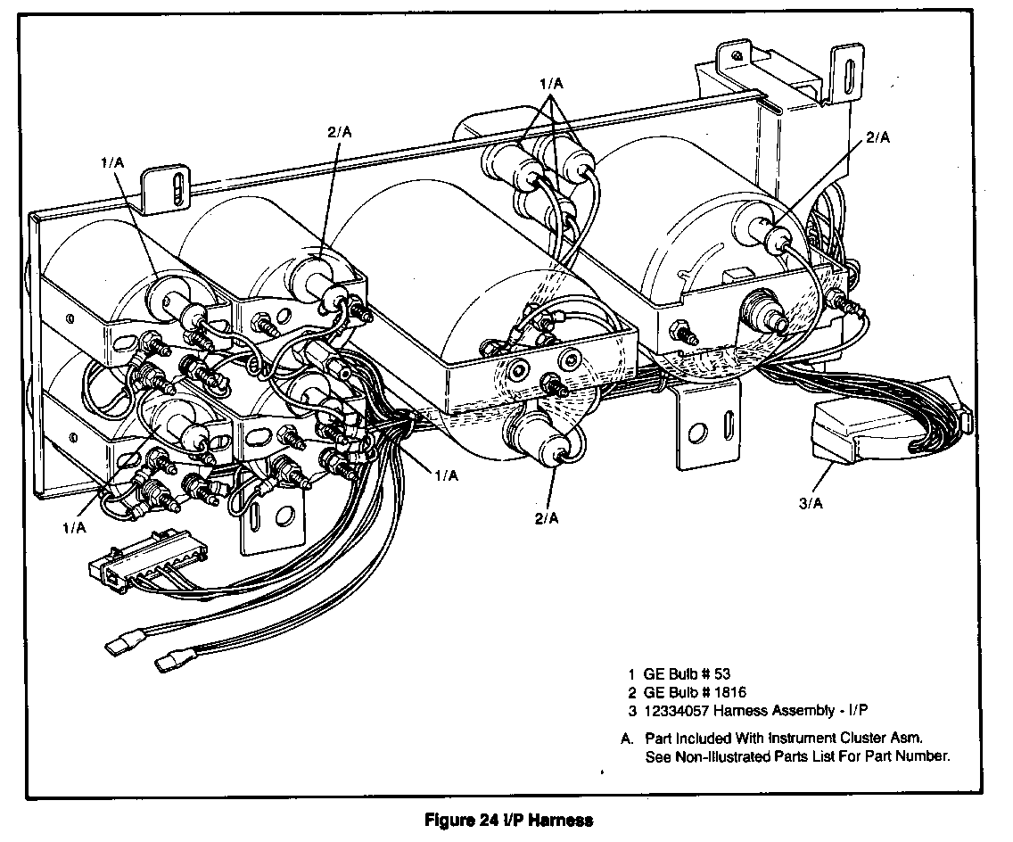
Bulb, Indicator Light Radio Shack #272-1137 Bulb, Hi-Beam and Turn Signal General Electric Trade #53
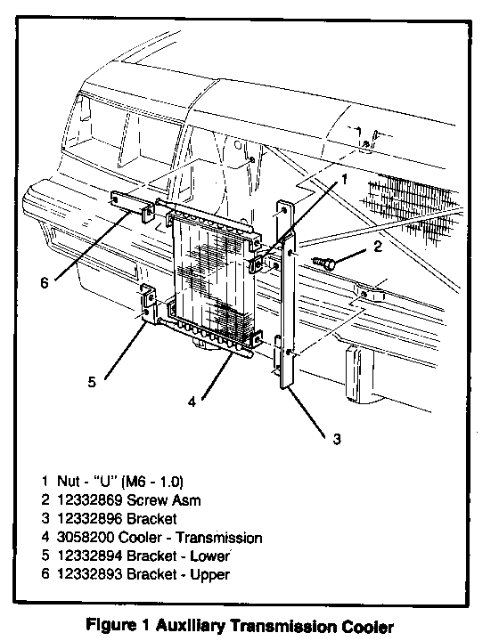
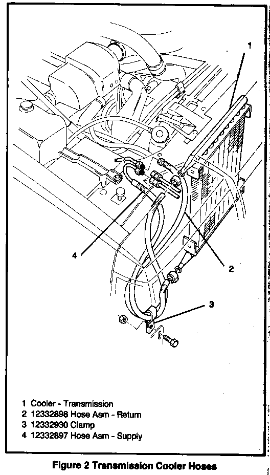
AUXILIARY TRANSMISSION COOLER
Remove or Disconnect See Figures 1 & 2
1. Grill. 2. Bolts attaching transmission cooler to mounting brackets. 3. Transmission cooler lines engine compartment. 4. Auxiliary transmission cooler.
Install or Connect
1. Auxiliary transmission cooler to mounting brackets. 2. Bolts. 3. Transmission cooler lines to cooler lines in engine compartment. 4. Check fluid level and add fluid as required. 5. Grill.
LADDER BAR
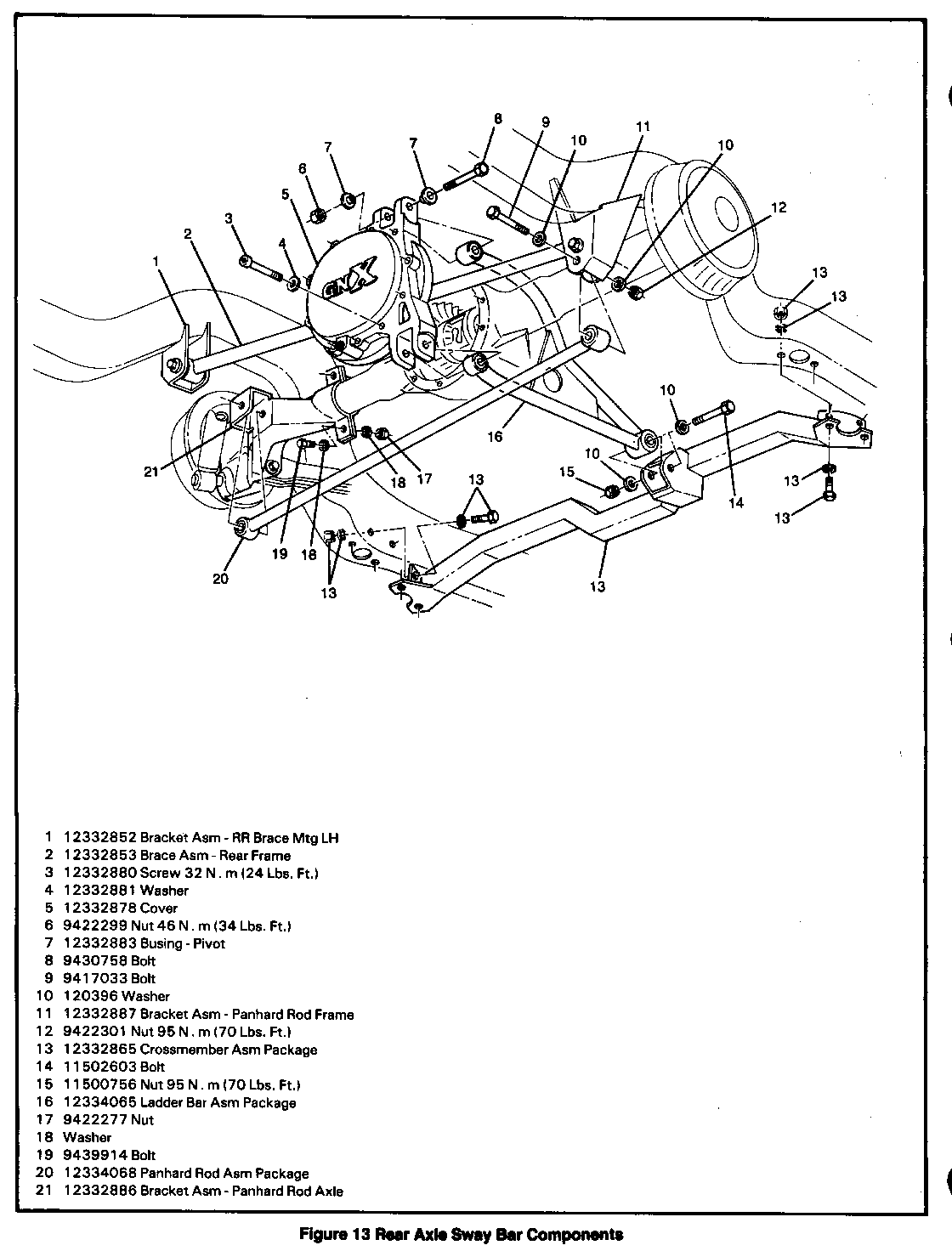
Remove or Disconnect (See Figure 13)
1. Rear wheels 2. Support rear axle and remove shock absorbers from axle. 3. Rear frame brace assy from left frame bracket. 4. Bolts attaching ladder bar to differential cover and to frame crossmember. 5. Ladder bar by pushing rearward to disengage from frame crossmember and then pull downward to disengage from differential cover.
Install or Connect
1. Ladder bar by engaging into differential then engaging into frame crossmember. 2. Bolts and nuts attaching ladder bar. o Ladder bar to differential cover nuts 46 N - m (34 lbs. ft.). o Ladder bar to frame crossmember nut 95 N - m (70 lbs. ft.). 3. Rear frame brace assy to left frame bracket with bolt and nut. o Rear frame brace assy mounting nut 95 N - m (70 lbs. ft.). 4. Shock absorbers to axle. 5. Rear wheels.
PANHARD ROD
Remove or Disconnect (See Figure 13)
1. Nuts and bolts attaching panhard rod to mounting brackets. 2. Panhard rod.
Install or Connect
1. Panhard rod to mounting brackets. 2. Bolts and nuts. o Nuts-95N-m(70lbs.ft.).
DIFFERENTIAL COVER
Remove or Disconnect (See Figure 13)
1. Raise car. 2. Panhard rod (see procedure). 3. Rear frame brace assy. 4. Ladder bar (see procedure). 5. Differential drain plug and drain lubricant. 6. Differential cover bolts. 7. Differential cover. o Both gasket sealing surfaces. o Degrease bolt surfaces using a non petroleum solvent.
Install or Connect
1. Apply loctite "N" type primer or equivalent to both sealing surfaces. 2. Apply a 3/16" bead of loctite # 518 or equivalent to differential sealing surface. 3. Differential cover to rear axle. 4. Bolts in a crosswise pattern and tighten to 32 N - m (24 lbs. ft.). 5. Differential drain plug and tighten to 18 N.m (13 lbs. ft.). 6. Ladder bar (see procedure). 7. Rear frame brace assy (see procedure). 8. Panhard rod (see procedure).
REAR FRAME BRACE ASSY
Remove or Disconnect (See Figure 13)
1. Nuts and bolts attaching rear frame brace assy to mounting bracket. 2. Rear frame brace assy.
Install or Connect
1. Rear frame brace assy to mounting brackets. 2. Bolts and nuts.
o Nuts - 95 N.m (70 lbs. ft.).
INSTRUMENT CLUSTER ASSEMBLY
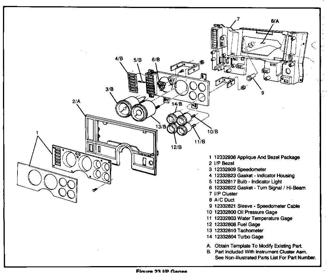
Remove or Disconnect (See Figures 22 & 23)
1. Left hand trim cover. 2. Screw attaching cluster to I/P. 3. Speedometer cable from the split in the engine compartment if two-piece cable is used or transmission in order to gain slack. 4. Steering column trim cover. 5. Lower the steering column. 6. Pull the cluster forward far enough to disconnect the speedometer cable, turbo vacuum line and all wire connectors. 7. Cluster assembly.
Install or Connect
1. Wire connectors, turbo gauge vacuum line and speedometer cable to cluster. 2. Push cluster into position on I/P. 3. Screws attaching cluster to I/P. 4. Raise the steering column. 5. Steering column trim cover. 6. Left hand trim cover. 7. Speedometer cable to the split in the engine compartment if two piece cable is used or transmission.
FUEL GAGE
Remove or Disconnect (See Figures 22 & 23)
1. Instrument cluster assembly (see procedure). 2. Nuts attaching wire leads to gage. 3. Lamp from gage. 4. Nuts and ground wire from gage bracket. 5. Fuel gage.
Install or Connect
1. Fuel gage to cluster. 2. Gage bracket to gage. 3. Ground wire and nuts to secure gage. 4. Wire leads to gage and secure with nuts. 5. Lamp to gage. 6. Instrument cluster assembly (see procedure).
TACHOMETER
Remove or Disconnect (See Figures 22 & 23)
1. Instrument cluster assembly (see procedure). 2. Lamp from tachometer. 3. Nuts from tachometer bracket. 4. Nuts attaching wire leads to tachometer. 5. Tachometer.
Install or Connect
1. Tachometer to cluster. 2. Wire leads to gage and secure with nuts. 3. Tachometer bracket to tachometer. 4. Nut to secure tachometer bracket. 5. Lamp to tachometer. 6. Instrument cluster assembly (see procedure).
OIL GAGE
Remove or Disconnect (See Figures 22 & 23)
1. Instrument cluster assembly (see procedure). 2. Nuts attaching wire leads to gage. 3. Lamp from gage. 4. Nuts and ground wire from gage bracket. 5. Oil gage.
Install or Connect
1. Oil gage to cluster. 2. Gage bracket to gage. 3. Ground wire and nuts to secure gage. 4. Wire leads to gage and secure with nuts. 5. Lamp to gage. 6. Instrument cluster assembly (see procedure).
SPEEDOMETER
Remove or Disconnect (See Figures 22 & 23)
1. Instrument cluster assembly (see procedure). 2. Lamp from speedometer. 3. Nuts and ground wire from speedometer bracket. 4. Speedometer.
Install or Connect
1. Speedometer to cluster. 2. Speedometer bracket to speedometer. 3. Ground wire and nuts to secure speedometer. 4. Lamp to speedometer. 5. Instrument cluster assembly (see procedure).
TEMPERATURE GAGE
Remove or Disconnect (See Figures 22 & 23)
1. Instrument cluster assembly (see procedure). 2. Nuts attaching wire leads to gage. 3. Lamp from gage. 4. Nuts and ground wire from gage bracket. 5. Temperature gage.
Install or Connect
1. Temperature gage to cluster. 2. Gage bracket to gage. 3. Ground wire and nuts to secure gage. 4. Wire leads to gage and secure with nuts. 5. Lamp to gage. 6. Instrument cluster assembly (see procedure).
TURBO GAGE
Remove or Disconnect (See Figures 22 & 23)
1. Instrument cluster assembly (see procedure). 2. Lamp from gage. 3. Nuts and ground wire from gage bracket. 4. Turbo gage.
Install or Connect
1. Turbo gage to cluster. 2. Gage bracket to gage. 3. Ground wire and nuts to secure gage. 4. Lamp to gage. 5. Instrument cluster assembly (see procedure).
General Motors bulletins are intended for use by professional technicians, not a "do-it-yourselfer". They are written to inform those technicians of conditions that may occur on some vehicles, or to provide information that could assist in the proper service of a vehicle. Properly trained technicians have the equipment, tools, safety instructions and know-how to do a job properly and safely. If a condition is described, do not assume that the bulletin applies to your vehicle, or that your vehicle will have that condition. See a General Motors dealer servicing your brand of General Motors vehicle for information on whether your vehicle may benefit from the information.
